Requirements Specification
Proposed
Project:
Dynamic Network Device Mapping System (DNDMS)
Clients:
Mr. Ken Swarner
Mr. Eric Crossman
Delivered
By:
SKYNET
Software
The
SKYNET Software Team:
Kevin Fealey
Heimdall Imbert
Stephanie Maloney
Trevor March
Andrew Warner
Dynamic Network Device
Mapping System (DNDMS)
Requirements Specification
Table of Contents
1. Product Overview and Summary
2. Development,
Operating, and Maintenance Environments
3. Data Flow
Diagrams (see attached Data Flow Diagram document)
4.5 Administrator Control Panel:
4.10 Department Head Floor Plan:
5.2 Functional Requirements Inventory:
7. Early Subsets
and Implementation Priorities
8. Foreseeable
Modifications and Enhancements
11.1 Cross Reference Index 24 -
11.3 Timeline (Gantt Chart) 25 -
1. Product
Overview and Summary
Our clients, Systems Administrators Ken
Swarner and Eric Crossman, have certain physical limitations when attempting to
recover information regarding components connected to the
The Dynamic Network Device Mapping System (DNDMS) will allow our clients to retrieve information regarding components connected to the network through a web-based building map, so that physical location of the user is irrelevant. Our clients will be able to gather information regarding a specific network device; add, delete, and edit information about devices; and edit user permissions.
There will be three user groups included in the DNDMS. Administrators will have access to all commands integrated into the application and will be able to view all devices connected to the network. The “Department Head” users group will be allowed to view the building map, but will only have access to see components connected within their area of the building. The “Faculty” users group will be further limited and see only devices within their office, as well as printers that they can use.
2. Development, Operating, and Maintenance
Environments
The Dynamic Network Device Mapping System
(DNDMS) will be developed on computers provided by
The Device Mapping System will be functional in at least 3 different web browsers: Microsoft Internet Explorer 7.0, Mozilla Firefox 2.0, and Apple’s Safari.
Information regarding maintenance will be discussed at a later time.
3. Data
Flow Diagrams
Please refer to Data Flow Diagram document.
4. Prototypes
The following prototype screens demonstrate how the functions of the system will be presented to the users. The design shown is flexible and by no means final; these only serve to better communicate in a graphical manner the functional requirements of the system.
4.1 Login Screen:
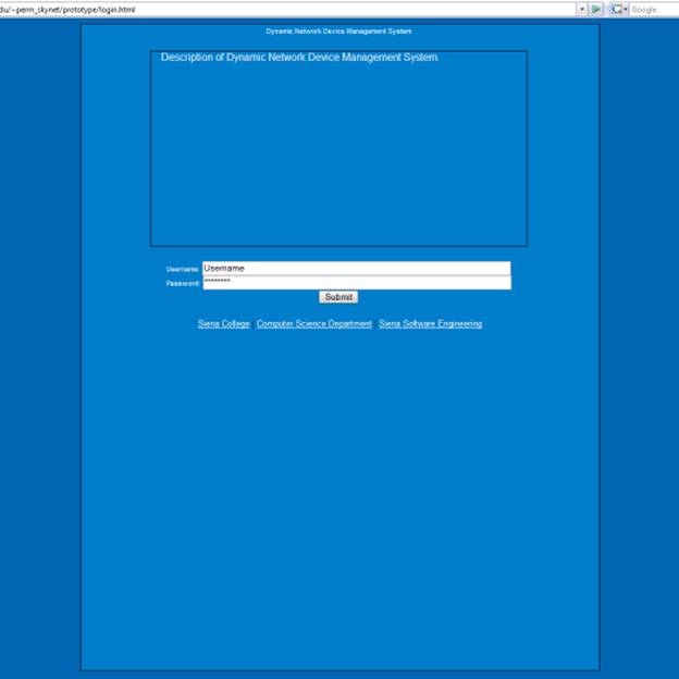
The login page has a description box to give the user(s) a
general overview of the purpose of the tool. The page then allows the user to
log on. There is also the feature of being able to go to the
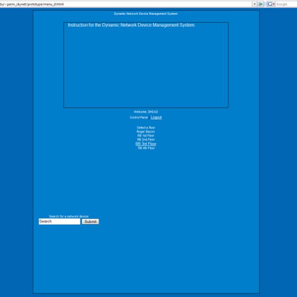
4.2 Administrator Menu:
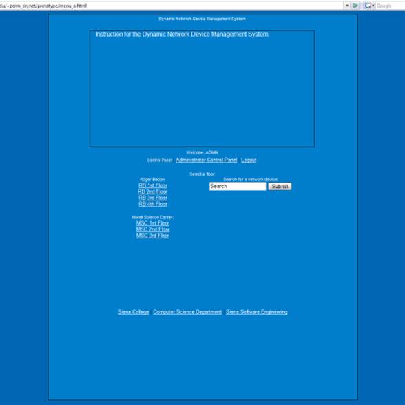
The menu page
will contain a basic instruction for how to navigate the floor maps and will
allow for the administrator to have access to all floors of Roger Bacon and
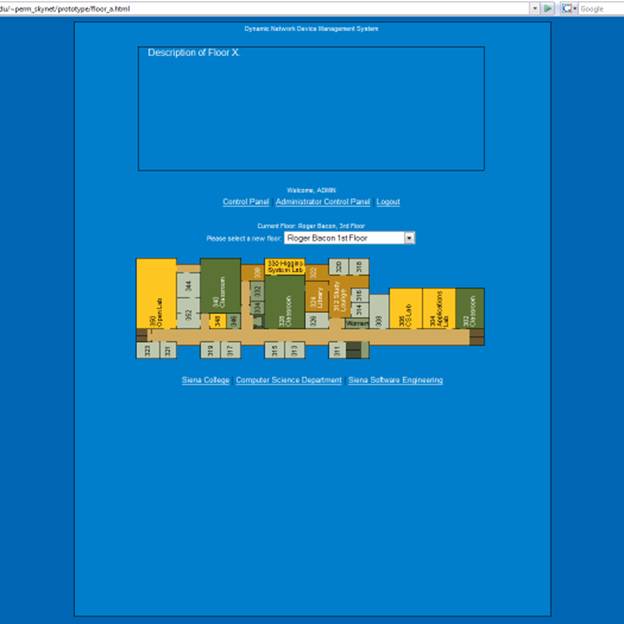
4.3 Administrator Floor Plan:
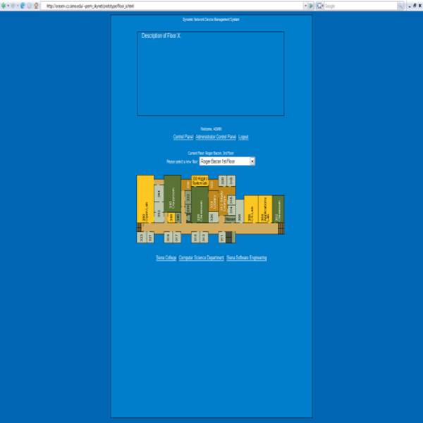
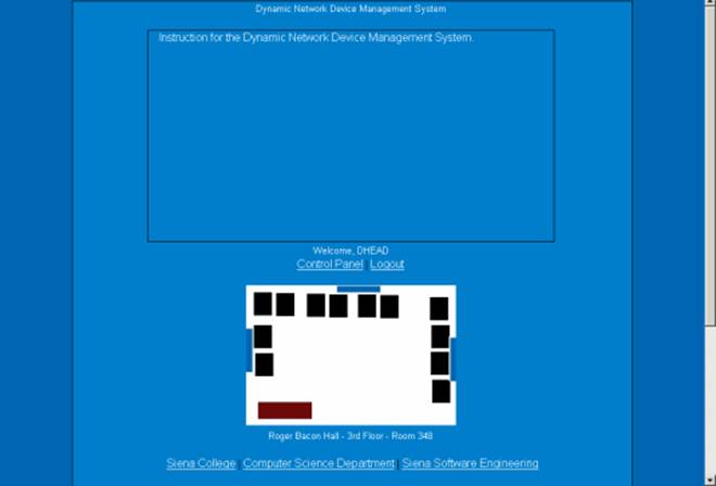
The administrator, department head and faculty members will all have the same view of the room page. The room page will have a description of the room and the layout for viewing. Since this page doesn’t allow any user to modify it and is simply for viewing purposes it will show up the same to all users who have access to the page.
4.5 Administrator Control Panel:
The administrator control panel is only accessible by the administrator and will have a simple description that explains how to perform edit users and devices. The administrator will be able to add new users and delete or view current users. The administrator will also be able to add, delete and view devices to rooms of their choosing.
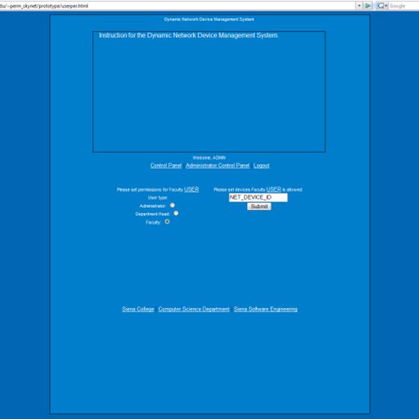
The permissions page is also only available by the administrator and allows the administrator to apply different user permissions to the users. The administrator will also be allowed to give users access to network devices.
4.7 Search Dialogue:
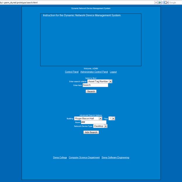
The search page is
an administrator only page that allows the administrator to quickly search
under any criteria he/she wishes. The administrator can search by the computers
asset tag number or but putting in the building, hall and floor number along
with the device they are trying to find.
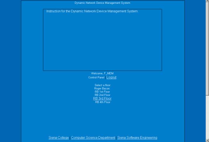
4.8 Department Head Menu:
The department head menu page is different
from the administrator page due to two considerable changes. The department
head will only have access to their own floor. In this case the department head
will only have access to the third floor of Roger Bacon. This page also
contains links to the three websites we have designated for all users to have
access to.
4.9 Faculty
Menu:
The faculty member will have the same access
on the menu page as the department head. They will have access only to one
floor whose description will show up in the description box. Since the
difference between the department head and the faculty member is based on the
rooms accessible on a floor, the access up to this point will not change and
will be first noticeable on the floor page.
4.10
Department Head Floor Plan
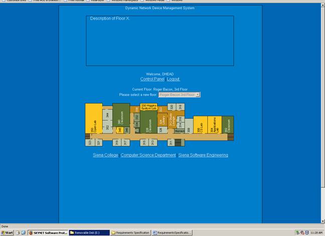
The floor page for the department head is almost identical to the administrators however the department head will only have access to their own floor and the drop down menu will not allow for them to change floors. The department head will be able to access any room on the floor by clicking on the room (including the hallway).
4.11
Faculty Floor Plan
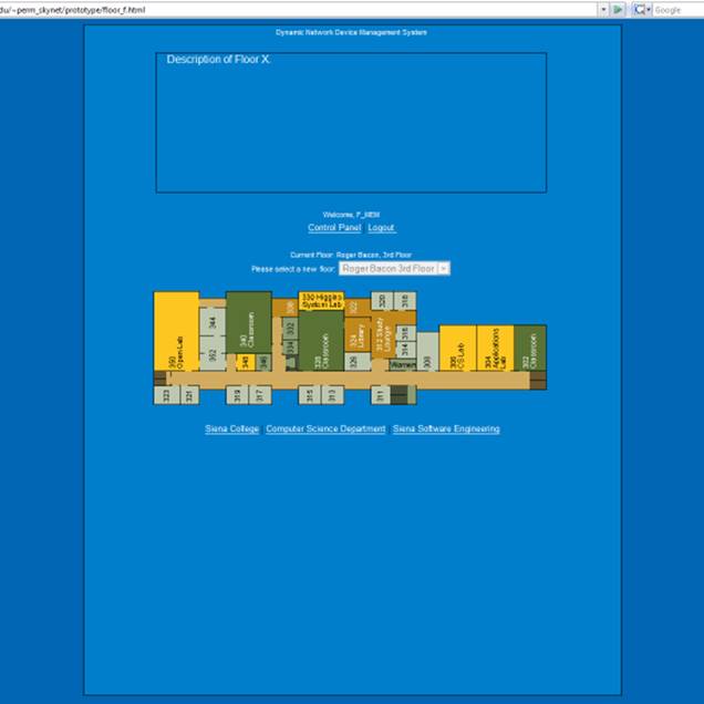
The floor page for the faculty member will
be much like the department heads’ view however they will only be able to click
their own room to access. They will also be able to click the hallway where
printers they use may be located.
5. Functional Requirements
5.1. Use-Case Analysis Narrative
SKYNET's Dynamic Network Device Mapping System will provide
functionality for three user groups; Administrator,
Department Heads, and Faculty.
Administrators will have all functions of the program
available to them at all times. When an Administrator logs in, he will be
presented with a screen displaying Roger Bacon and
The Administrator will be
given access to make additions and subtractions from the current
When an Administrator wants to
find a specific computer within the
An Administrator will also
have the ability to add and remove Department
Heads and Faculty from the
DNDMS. If a new user is hired, the Administrator can add a new user and
choose that new user’s permissions.
Alternatively, if a user leaves
Department Heads will be able to view the network devices in
their entire department. Department Heads
will not be able to make any changes to the floor plan, but can view all
components, within their department, connected to the
Faculty, which includes anyone who works in the
5.2. Functional
Requirements Inventory
The following list outlines the required functionality to be included in the final solution. The requirements are listed according to user case and then by screens the user will view.
General:
The Dynamic Network Device Mapping System is web-based.
Administrator User:
The Administrator user will have an account.
The Administrator user will have a username and password.
The Administrator will establish usernames and passwords for other users.
Login Screen:
The user will log in with correct username and password.
An incorrect login will provide an appropriate error message.
Welcome Screen:
The user will have access to a control panel on the welcome screen.
The user will be able to perform a search for certain devices or a specific device based on indicated search criteria.
The user will be able to select a floor of Roger Bacon Hall from a menu to view a floor plan layout.
The user will be able to select a floor of
The user will be able to logout from the welcome screen by clicking the "Logout" link.
Control Panel Index Screen (Administrators only):
The user will be able to change user passwords in the control panel.
The user will be able to change user permissions for devices in the control panel.
The user will be able to insert notes pertaining to a specific room or devices within a room.
The user will be able to log out from the control panel index screen.
User Control Panel Screen:
The Administrator user will be able to choose a user for which the password is to be changed.
The Administrator will enter a new password for the chosen user.
The Administrator will submit changes.
A message will appear indicating that a change has been accepted.
The Administrator user will be able to log out from the user control panel screen.
User Permissions Control Panel Screen:
The Administrator will be able to choose a user for which the permissions are to be set.
The Administrator will be able to search for or choose a device or set of devices for which the user’s permissions are to apply.
The Administrator will be able to choose the permission level for the user with reference to the chosen device(s): read or restrict.
The Administrator will submit the changes.
A message will appear indicating that a change has been accepted.
The Administrator user will be able to log out from the user permissions control panel screen.
Room Notes Control Panel Screen:
The Administrator user will be able to choose a building and floor for the corresponding room.
The Administrator will be able to enter a room number for which to add notes.
The Administrator will be able to add notes into a text box for the chosen room.
The Administrator will submit the changes.
A message will appear indicating that a change has been accepted.
The Administrator user will be able to log out from the room notes control panel screen.
Floor Plan Screen:
A floor plan for the chosen floor will be displayed on the screen.
The building name and floor number will be displayed on the screen.
The Administrator user will be able to access the control panel from this screen.
Administrator user will be able to view information about all rooms and devices on the floor.
The Administrator will be able to choose a room from the floor plan to view a detailed room layout.
The Administrator user will be able to choose a different
floor of either Roger Bacon Hall or
The Administrator user will be able to log out from the floor plan screen.
Room Layout Screen:
A room layout will be displayed for the selected room.
The existence and location of devices within the room will be indicated in the layout.
The building name, floor number, and room number will be displayed on the screen.
The Administrative user will be able to zoom out to the floor level diagram to which the room belongs.
The Administrator user will be able to choose a device within the room to view the information pertaining to that device.
The information for a specific device will appear below the room layout in a text box.
Any available notes for the selected room will be displayed on the screen for easy reference.
A legend will be displayed below the layout to denote the meaning of symbols in the layout.
The Administrator user will be able to log out from the room layout screen.
Search Screen:
The Administrator user will be able to search for a device on the following criteria:
Asset Tag Number
MAC Address
Serial Number
Summarized search results will be displayed on the same screen.
Search results will be selectable to view more detailed results.
When selected, detailed search results will be displayed in the room layout view.
Faculty/Staff User:
The Faculty/Staff user will have an account established by the Administrator.
The Faculty/Staff user will have a username and password.
Login Screen:
The user will log in with correct username and password.
An incorrect login will provide an appropriate error message.
Welcome Screen:
The user will be able to select a floor of Roger Bacon Hall from a menu to view a floor plan layout.
The user will be able to select a floor of
The user will be able to logout from the welcome screen by clicking the "Logout" link.
Floor Plan Screen:
A floor plan for the chosen floor will be displayed on the screen.
The building name and floor number will be displayed on the screen.
Faculty/Staff user will be able to view information about devices within their office and printers accessible to them.
Rooms available for viewing will be highlighted so a Faculty/Staff user is aware of which rooms can be selected.
The Faculty/Staff will be able to choose a room from the floor plan to view a detailed room layout.
The Faculty/Staff user will be able to choose a different
floor of either Roger Bacon Hall or
The Faculty/Staff user will be able to log out from the floor plan screen.
Room Layout Screen:
A room layout will be displayed for the selected room.
The existence and location of devices within the room will be indicated in the layout.
The building name, floor number, and room number will be displayed on the screen.
The Faculty/Staff user will be able to zoom out to the floor level diagram to which the room belongs.
The Faculty/Staff user will be able to choose certain devices within the room to view the information pertaining to that device.
The information for a specific device will appear below the room layout in a text box.
Any available notes for the selected room will be displayed on the screen for easy reference.
A legend will be displayed below the layout to denote the meaning of symbols in the layout.
The Faculty/Staff user will be able to log out from the room layout screen.
Department Head User:
The Department Head user will have an account established by the Administrator.
The Department Head user will have a username and password.
Login Screen:
The user will log in with correct username and password.
An incorrect login will provide an appropriate error message.
Welcome Screen:
The user will be able to select a floor of Roger Bacon Hall from a menu to view a floor plan layout.
The user will be able to select a floor of
The user will be able to logout from the welcome screen by clicking the "Logout" link.
Floor Plan Screen:
A floor plan for the chosen floor will be displayed on the screen.
The building name and floor number will be displayed on the screen.
Department Head user will be able to view information about devices within their entire department.
Rooms available for viewing will be highlighted so a Department Head user is aware of which rooms can be selected.
The Department Head will be able to choose a room from the floor plan to view a detailed room layout.
The Department Head user will be able to choose a different
floor of either Roger Bacon Hall or
The Department Head user will be able to log out from the floor plan screen.
Room Layout Screen:
A room layout will be displayed for the selected room.
The existence and location of devices within the room will be indicated in the layout.
The building name, floor number, and room number will be displayed on the screen.
The Department Head user will be able to zoom out to the floor level diagram to which the room belongs.
The Department Head user will be able to choose certain devices within the room to view the information pertaining to that device.
The information for a specific device will appear below the room layout in a text box.
Any available notes for the selected room will be displayed on the screen for easy reference.
A legend will be displayed below the layout to denote the meaning of symbols in the layout.
The Department Head user will be able to log out from the room layout screen.
The Dynamic Network Device Mapping System will be designed to run on Internet Explorer 7.0, Firefox 2.0, and Safari 2.0.
The Dynamic Network Device Mapping System will be designed to be viewable on a computer monitor resolution of 1024 x 768 pixels.
7. Early Subsets and Implementation
Priorities
The essential components of this system are:
- The ability to show computer attributes and locations on floor maps, navigate the maps and zoom into the floor maps to a room level.
- The ability of the Administrator to add, remove, and move devices to the floor maps.
- The ability for Administrators to set other user permissions.
- The ability for Department Heads to view the network devices in their entire department.
- The
ability for Faculty to view their office network devices and the printers
that are available to them.
8. Foreseeable Modifications and
Enhancements
While this system is in development, and once it is completed, additional functionality may be added. We could potentially make it available for additional floors and buildings to be added later. Additionally, the team would work to make the software compatible with newer versions of browsers that are released after the software is released.
The Web Application Interface will be designed for multiple types of Users (Faculty, Department Head, and Administrator). (Please see Use Cases for more detailed User information). Each specific User will need to have certain abilities. The Users and abilities are outlined below. The Functional Requirements (Please reference Section 5) will also be revisited upon acceptance to ensure that all desired features have been included.
Faculty User(s)
- Navigate to Team SKYNET’s Webpage
- Login
- View Office Map
- View Layout of own office
Department Head User(s)
- Navigate to Team SKYNET’s Webpage
- Login
- View floor plan
- View layout of own office
- Edit aspects of specific offices
Administrator User(s)
- Navigate to Team SKYNET’s Webpage
- Login
- View floor plan
- View device information
- View layout of a specific floor
- View layout of all offices
- View layout of a specific office
- Edit aspects of all offices
- Edit/Add/Delete User(s)
- Edit User(s) passwords
- Edit room layout(s)
- Edit device information
- Set User(s) permissions
A full test plan will be designed and implemented to be delivered with the final solution. Included in the test plan will be the unit test, the integration test, the system test, and the acceptance test. Specifically, the system will be tested to ensure that the data contained in the databases is only accessible to the specific users that have been given access. The system will also be tested to ensure that the login is secure, and that only authorized users
will be able to login. Testing will also be done to ensure that only administrative users will be allowed to edit data. Finally, the system will be tested to ensure that the correct data is displayed properly, and in the correct location.
11. Appendix 11.1 Cross Reference Index A Cross Reference Index will be provided in the preliminary design phase once all items and processes have been identified. 11.2 Glossary of Terms Data Flow Diagram - A graphical representation of the flow of data through an information system.
Database – A structured collection of records or data.
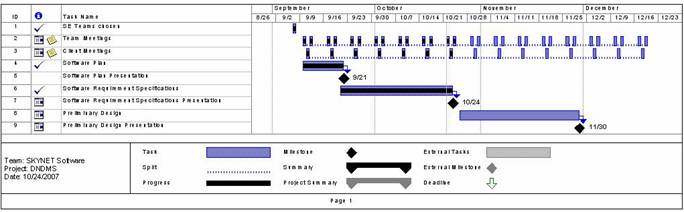
Gantt Chart - A type of bar chart that illustrates a project schedule.
Linear Sequential Model / Classic Waterfall Model – A sequential software development model in which development is seen as flowing steadily downwards (like a waterfall) through various phases.
Media Access Control (MAC) - A data protocol that provides addressing and channel access control mechanisms that make it possible for several terminals or network nodes to communicate within a multipoint network (typically a local area network (LAN)).
MAC Address - A 48-bit hexadecimal (12 characters) number given to a device in a network.
The address is normally assigned to a device, such as a network card, when it is manufactured. Local Area Network (LAN) - A small computer network covering a small geographic area like a home, office, or building(s).
Component / Device - Any physical piece of a computer, including the circuitry inside of it.
Network Device - A component/device that is on a network (Printer, computer, scanner, etc.).
Prototype – An original type, form, or instance of an object serving as a typical example or standard for other objects of the same category.
Virtual - An entity that exists in a form that is not natural.
Users Group - A collection of logins that will have the same permissions given to them.
11.3. Timeline (Gaant Chart)