Preference Screen:
monitored computer only
NOTICE: Do not register the device unless this computer will
be the computer with sensors attached to it!!
Contact Information:
First Name:
Last Name:
Address Information:
Street:
City: State: Zip:
Phone: - ext:
Account Information:
E-mail:
Password: Retype Password:
Security Question: ?
Answer:
Monitoring Location:
Notification Information:
E-mail Address: Same as above
Cell Phone: -
Default: Cell
Phone E-mail
The Preference screen appears when a first time user registers. This page provides the system with all contact, user account, and notification information about the user. The contact information will be used for billing and contact in emergency situations. The account information involves creating a password and choosing a security question incase the user loses their password. The notification information is used to alert the user when there are errors with the system, a threshold point is met by one of the sensors, or one of the sensors is malfunctioning.
Initial Screen:
Welcome
Mr. Ken Swarner
you are located at: Home IP: 192.168.0.1
You currently have no sensors registered. Click here to
register a sensor.
This screen is shown when the user has first logged in. Their name, derived from the information the user provided, will be shown along with the location the user is at and their IP address. Since the user is at the monitored machine they will be able to change their profile and add sensors.
Registrant Sensor Screen:
Owner of Sensor:
Location:
IP Address:
Operating System:
Sensor Type:
The register screen appears when the user clicks on the “Register a sensor” link. It requires the user to enter the location of the given sensor, who the owner is, and the type of sensor it is. The IP address and Operation System field will be auto-filled by our PHP code.
Monitored User Screen:
Welcome
Mr. Ken Swarner
you are located at: Home IP: 192.168.0.1
Sensors:
Temperature Sensor Office Status: ACTIVE
Current
Temperature: 55˚F
Motion Sensor Home Status: ACTIVE

Water
Sensor Home Status: DISABLED
ERROR
– Device is not responding
Click here to register/delete a sensor.
This screen is the Monitored User screen, users will see this populated with some examples of sensors. The user is able to edit their personal profile. They are also able to view the history of the sensor data, change the settings on a specific sensor and view the status and readings from the sensor. Each sensor will have different data to display and different settings. There is a link to refresh the sensors incase one is not working properly or the browser window has been open for a longer period of time. There is also a link for the user to add more sensors or delete the sensors. The user can only delete a sensor or change the sensors setting from the computer the sensor is installed on.
Remote User Screen:
Welcome
Mr. Ken Swarner
you are located at: Remote IP: 66.125.8.10
Sensors:
Temperature
Sensor Office Status: ACTIVE
Current Temperature: 55˚F
Motion Sensor Home Status: ACTIVE
Water
Sensor Home Status: DISABLED
ERROR-
Device
is not responding
Click here to register/delete a sensor.
This screen is what the user will see logged onto the system from a remote computer. The remote user will unable to edit their profile or the settings on the sensors. They will be able to access the history of the sensors, refresh the devices and add sensors to their remote machine. Once they add a sensor to the remote machine, it is now considered a monitored machine and the screen will change to the Monitored User Screen.
Sensor Options Menu:
monitored computer only
Temperature
Sensor
Current
Temperature: 72˚ F
Threshold: ˚F
ENABLE DISABLE
When the sensor
option button is pressed on the Monitored User Screen this screen will
appear. This screen will be different
for the different types of sensors. As
an example, the temperature sensor is used.
It will show the information the sensor is currently reading. The threshold temperature will be shown; when
the temperature exceeds this threshold a notification is sent to the user. Also the user can enabled or disabled the
sensors depending on what information the user wants available remotely.
Alert History Screen
Alerts: 1
19:48:00
19:49:00
When the Alert History Screen is pressed, this Alert History Screen will appear. The temperature sensor is used for this example. When the temperature exceeds the threshold then an alert is triggered. The user will be able to see when the alert was triggered and the successive times the temperature is over the threshold. When the temperature dips below the threshold then the tracking of that temperature stops.
Personal Profile Screen
The user will come
to this screen by pressing the Personal Profile Buttons. The buttons let you change information about
your account. The account information
button lets the user change their e-mail, password, security question,
etc. The change contact information
button lets the user change their phone number, home address, and that type of
information. Finally the Change
notification information button lets the user change how they will be contacted
when a problem arises.
Dataflow Diagrams:
Context Diagram:

This is the context diagram. This is the most basic diagram that describes how the user will interact with the system.
Level 0:
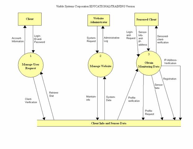
This is the level 0 diagram. This diagram is an expansion of the “Environmental Monitoring System” process from the context diagram.
Level 1:
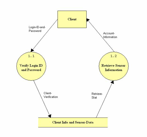
This Level 1 diagram shows the “Manage User Request” process.
Level 3:

This shows the process for the “Obtain Monitoring Data” method.
Level 3.1:
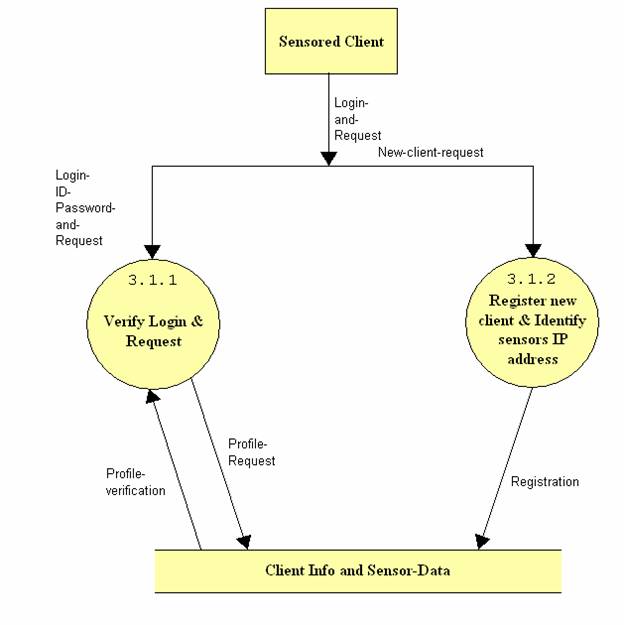
This shows the process for the “Verify Login and Process Request” method.
Section 4: Functional Requirements
Use-Cases:
Remote Client
·
An online page to login.
·
An online page that displays archived and current information from the
sensors
Monitored Client
·
An online page to login.
·
An online page that displays archived and current information from the
sensors
·
An online page that will allow for changes to user profile
·
An online page that will allow for changes to sensor preferences
Administrator
·
An online page to login
·
An online page to access logged data related to users
·
An online page to access logged data related to attached devices
Narrative:
The Environmental Monitoring System will be a web based application that will allow management of a user’s account and the retrieval of recorded information such as the temperature, water level, a live video feed to be updated at set intervals as well as an archived history or alerts. Users logging into the site from a registered monitored location will have the ability to make changes to the preferences of local monitoring devices. Users logging into the system from a remote location will only have the ability to view the information related to their account. Users will receive notification via e-mail or text message in the event of monitoring devices failing, or when user defined constraints are violated such as a max/min temperature etc. Users will also receive notifications when personal information is changed to ensure the integrity of the system. To ensure a live connection with the monitored environment a ping like utility will be incorporated into the server application to periodically test for a live connection. The IP address of the monitored system will be recorded and regularly updated to easily identify remote logins.
Section 5: Performance Requirements
The Environmental Monitoring System will be able run on
Windows, Macintosh, and Linux platforms.
The Environmental Monitoring System will be accessible
through Microsoft Internet Explorer 6.0, Netscape Navigator 7.1, Mozilla
Firefox and Opera.
The Environmental Monitoring System will be designed to be
viewable at 1024 by 768 screen resolution on a computer monitor.
The Environmental Monitoring System will be running on a
Linux server with Apache Webserver, PHP, and MySql.
Section 6: Exception Handling
While using the
Environmental Monitoring System, there might be some unexpected circumstances
that will cause errors. The system must
be ready to handle some of these exceptions/errors.
User forgets their password:
The user forgetting
their password should be an exception the system must handle. The system will be able to handle this
because when the user registers, they are asked to pick a security question and
provide an answer. The link that is on
the log in page will allow the user to recover their password securely.
A sensor stops working:
It is possible that
one of the sensors will malfunction and the system must handle this. If there were an error with a sensor the
system would notify the user via what notification medium they picked and state
the error on the sensor information screen.
Possibly the system would let the Software administrator know if there
were a sensor malfunction.
Our team will
extensively test our system in order to ensure these exceptions/errors are
handled appropriately and any other exceptions found will be handled.
Section 7: Early Subsets and Implementation Priorities
The most essential components of the system are:
· To allow the user to register various sensors.
· To allow the user to oversee the properties and information of each individual sensor.
· Issue an alert to the user by e-mail or text message in the case that a device has detected a
problem.
· To allow the user to carry out these actions securely.
All features discussed
above and in the functional requirements have been requested by Mr. Ken Swarner
and Dr. Tim Lederman and will be implemented in this project.
Section 8: Foreseeable Modifications and Enhancements
While developing
this system additional functionality might be discovered and could be included
in a future versions. One enhancement
the team and client discovered was sharing sensors between users. This would enable one user to give permission
to another user to view their sensor’s information. Another enhancement would
be additional sensors. Temperature and webcam/motion sensors are the minimum
but there are more sensors that could be added to this system. The client expressed interest in modifying
the interface to different handheld devices in addition to the plain
website. These handheld devices would
include web enabled cell phones, PDAs, and blackberries.
Section 9: Acceptance Criteria
At this part in the development process our web site contains nine screens. These screens are the log in screen, preference screen, initial screen, registrant sensor screen, monitored user screen, remote user screen, sensor options menu, view alert screen, and user preferences screen.
1. Log in screen
- can the user log in
- does the forget password link work
- can the user register if they are a new user
- is the current news being displayed
- does the more news link work
2. Preference screen
- can all the fields be filled in
- do the submit and cancel buttons work properly
3. Initial screen
- does the location and IP address display correctly
- can the user view their personal profile
- can the user log out
- does the register sensor link work
4. Registrant sensor screen
- can all the fields be filled in
- do the OS and IP fields auto fill
- do the submit and cancel buttons work properly
5. Monitored user screen
- does the location and IP address display correctly
- can the user view their personal profile
- can the user log out
- do the correct sensor(s) show up on the screen
- can the alert history be viewed for each sensor
- can the device options be viewed for each sensor
- does the current sensor information load
- does the refresh devices link work
- can the user register or delete a sensor
6. Remote user screen
- does the location and IP address display correctly
- can the user log out
- do the correct sensor show up on the screen
- can the alert history be viewed for each sensor
- does the current sensor information load
- does the refresh devices link work
- can the user register or delete a sensor
7. Sensor options screen
- can the threshold be changed
- can the sensor be enabled and disabled
- do the submit and cancel buttons work
8. View alert screen
- do the alerts show up
9. User preference screen
- can the user change their account information
- can the user change their contact information
- can the user change their notification information
Section 10: Testing Requirements
All aspects of the Environmental Monitoring System will be thoroughly tested to ensure that all data submitted by the user is stored to the appropriate database table(s). In addition, the system will be tested to ensure that the data stored in the database is secure and not available to outside users. We will also test to make sure that the same IP address cannot be registered more than once. The team members will also test all matching functions, administrative functions, and communications between the system and users.
Section 11: Design Hints and Guidelines
The Environmental Monitoring System will use a web interface that will allow users to view recorded information, and depending on their locations, also change preferences and user information. Users will have restricted abilities when logging into the system from a registered monitored location. Using PHP we will need to log the IP address of registered computers in a database that needs to be regularly updated via software located on the user’s computer. At each login the user’s current IP address would be checked against those stored in the database to determine whether their user status as a remote user.
Section 12: Cross Reference Index
This section will be available once we finalize a complete set of data flow diagrams in the design phase of the project.
Section 13: Glossary of Terms
Database – A collection of data arranged for ease and speed of search
and retrieval.
IP Address – Each machine
connected to the Internet has an address known as an Internet Protocol address
that takes the form of four numbers separated by dots, for example:
123.45.67.890.
Monitored Computer – Refers to the computer in which a sensor is attached and
registered.
PHP- The PHP Hypertext Preprocessor is a programming language
that allows web developers to create dynamic content that interacts with
databases.
Remote Computer – Refers to a device or computer other than the monitored
computer that a user uses to access their account. Sensors are not
attached to these devices or computers and therefore, users can only access
their account information.
Threshold – The point that must be exceeded to begin producing a given
effect or result.
Web Application - An application delivered to users from a web server over a network such as the World Wide Web.
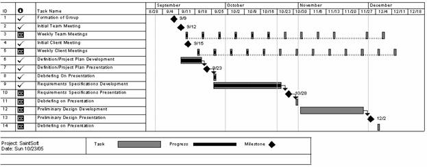
Section 14: Gantt Chart