Requirements Specification
Requested by: Mr. Ken
Swarner
Systems
& Operations Manager
Mr.
Eric Crossman
Assistant
Systems & Operations Manager
Virtual
Network Device Mapping System
Prepared by:
MAJIK Software Solutions
Amanda Danko
Kevin Johnson
Ian Kost
Kelly Morgan
Mark Riley
Requirements Specification
Table of Contents
1. Product Overview and Summary
2. Development,
Operating, and Maintenance Environments
3.5 Special User Functionality
5. Functional
Requirements Inventory
7. Early Subsets
and Implementation Priorities
8. Foreseeable
Modifications and Enhancements
1. Product Overview and Summary
Devices on the network throughout the
2. Development, Operating, and Maintenance
Environments
The guidelines set by our clients Mr. Ken Swarner and Mr. Eric Crossman will help us to develop the Mapping System. Using the Siena College Software Engineering workstations, a Dell running Windows XP and an iMac, we will create a web-based program with a graphical interface. An Oracle 10G Release 2 database will also be created to store the information about the network devices. Users will then login to the website which will be run on an Apache web server.
The Device Mapping System will be functional in 4 different web browsers. These web browsers are Internet Explorer 6.0, Safari, Mozilla version 1.6 or greater and Mozilla Fire Fox version 1.5 or greater.
The Data Flow Diagrams show a graphical breakdown of the processes and major flows of data that occur in the system. The Administrator has a completely different set of process than the Faculty and Special Users. The Administrator can edit information in the program. All the users have the option of looking at layouts and device information specific to their account information. The Special User can only view information that the Administrator has set up for them to view and Faculty can only view their room layouts. The Administrator has unlimited access.
The Virtual Network Device Mapping System will service three users.
The Administrator user will have full access to all features of the software, including the ability to view and edit all information regarding each device on the network. The administrator user will manage all other user accounts.
A Faculty/Staff user will only have the option to view information about devices pertaining to them (i.e. their office and/or classrooms, etc.). The Faculty/Staff user will have no editing capability.
The Special user's use of the system will vary. The Special user will be granted use of certain features of the system by the administrator as needed, including extended view of information about devices and possible editing capabilities.
The Administrator Functions diagram is a Level 1
Diagram. It shows the “Manage Website”
process.
This is a level 2 diagram that shows the “Manage User
Request” process for faculty members.
3.5 Special User
Functionality
This
diagram shows the “Manage User Request” process for a Special User.
The following prototype screens demonstrate how the functions of the system will be presented to the users. The design shown is flexible and by no means final; these only serve to better communicate in a graphical manner the functional requirements of the system.
This is the first page that all users see when using the
program. It gives a short description of the purpose of the program, followed
by the login dialogue. This page also links to the websites of Team MAJIK via
the team logo link,
This is the first page a user will see after logging in.
Administrative users will see the Control Panel link as displayed, and all
other users will not. Otherwise, the page displays the same for all users.
Brief directions concerning use of the program are displayed for new or
unfamiliar users. Also, Roger Bacon Hall and the
The Floor Plan page indicates the building and floor currently displayed. Immediately below, the physical layout of that floor is graphically displayed. Users can select individual rooms in order to be brought to a closer view. Certain users may be restricted from viewing all rooms on a floor. For example, professors may only be able to view their own office, and not those of their colleagues. These restrictions will be determined by the Administrative user, who can view all information.
The Room Layout page gives a close-up view of an individual room. It displays the location of all network devices in the room graphically. The devices are displayed as symbols which are defined in a legend beneath the Room Layout image. Each device can be selected by a user, causing information pertaining to that device to be displayed in a text box at the bottom of the page. Also, a link is displayed allowing a user to quickly zoom out to the Floor Plan they were viewing before selecting that room.
This page contains a menu detailing Administrative tasks. It can be accessed only by an Administrative user. Choosing a menu option will cause the dialogue related to that action to display below the menu. This image is shown with the Roger Bacon drop-down menu extended, and the Passwords menu option selected.
This image is a depiction of possible Search options available to all users. They would be able to enter a string to be searched, and if desired use the Advanced Options to narrow that search. When using the Advanced Options it would not be necessary to enter a string into the Search box, or to make use of all of the Options. This dialogue will be displayed on all screens after logging in, for all users.
5. Functional
Requirements Inventory
The following list outlines the required functionality to be included in the final solution. The requirements are listed according to user case.
- The Virtual Network Mapping Device System is web-based.
- The Index page displays a login screen common to all users.
- All pages other than the Index page display a "Logout" option for all users.
Administrative User:
- Once logged in, an Administrator will be able to access the Control Panel from any page.
- The Control Panel will provide functionality for editing information and accounts, including:
- Editing a password for any user.
- Editing user permissions.
- Editing floor plans.
- Editing room layouts.
- Editing device information.
- Editing notes pertaining to specific rooms.
- Will
be able to select a specific floor of either Roger Bacon Hall or the
- A menu presented on the first page after logging in.
- A drop-down menu present on all pages after logging in.
- Will then view a Floor Plan for the selected floor.
- Will be able to view all information presented by the program in any view, including all offices, classrooms, devices, and device information.
- Individual rooms will be selectable from the Floor Plan.
- A Room Layout will appear, displaying the location of network devices in that room.
- A "Zoom Out" link will be displayed, allowing quick return to the previous Floor Plan.
- A legend will be displayed beneath the Room Plan to denote the meaning of symbols.
- Network devices may be selected from the Room Layout, displaying the information about that device in a text box below the legend.
- Will be able to Search for devices based on optional criteria. The specific Search options will be determined at a later date.
Faculty/Staff User:
- Will
be able to select a specific floor of either Roger Bacon Hall or the
- A menu presented on the first page after logging in.
- A drop-down menu present on all pages after logging in.
- Will then view a Floor Plan for the selected floor.
- Individual rooms will be selectable from the Floor Plan.
- May only be able to select certain rooms based on Permissions set by Administrative user.
- A Room Layout will display the location of network devices in that room.
- A "Zoom Out" link will be displayed, allowing quick for return to the previous Floor Plan.
- A legend will be displayed beneath the Room Plan to denote the meaning of symbols used.
- Network devices will be selectable from the Room Layout, displaying the information about that device in a text box below the legend.
- Will be able to Search for devices based on optional criteria. The specific Search options will be determined at a later date.
Special User:
- Will be able to use any feature that the Administrator grants access to.
The Virtual Network Device Mapping System will be designed to run on Internet Explorer 6.0, Firefox 1.5, and Safari 1.2.
The Virtual Network Device Mapping System will be designed to be viewable on a computer monitor resolution of 1024 x 768 pixels.
7. Early Subsets and Implementation
Priorities
The essential components of this system are:
- The ability to show computer asset locations on floor maps, and navigate the maps.
- The ability to set what objects are visible to each user.
- The ability of the administrator to edit the assets.
8. Foreseeable Modifications and
Enhancements
While this system is in development, and once it is completed, additional functionality may be added. One possibility was making the system open-ended, so that additional floors and buildings could be added later. Additionally, the team would work to make the software compatible with newer versions of browsers that are released after the software is released.
The web interface will be designed for multiple types of users. (See Use Cases for more detailed user information). Each user will need to have specific abilities. The users and abilities are outlined below. The functional requirements (Section 5) will also be revisited upon acceptance to ensure that all desired features have been included.
Faculty/Staff User
- Login
- Navigate to team’s webpage
- Navigate to software engineering webpage
- View Floor Plan
- View Layout of own office
Special User
- Login
- Navigate to team’s webpage
- Navigate to software engineering webpage
- View floor plan
- View layout of own office
- Edit aspects of specific offices
Administrator User
- Login
- Navigate to team’s webpage
- Navigate to software engineering webpage
- View floor plan
- Zoom
- View device information
- View layout of all offices
- View layout of a specific floor
- View layout of a specific office
- Edit aspects of all offices
- Edit user passwords
- Set users permissions
- Edit room layout
- Edit device information
A full test plan will be designed and implemented to be delivered with the final solution. Included in the test plan will be the unit test, the integration test, the system test, and the acceptance test. Specifically, the system will be tested to ensure that the data contained in the databases is only accessible to the specific users that have been given access. The system will also be tested to ensure that the login is secure, and that only authorized users will be able to login. Testing will also be done to ensure that only administrative users will be allowed to edit data. Finally, the system will be tested to ensure that the correct data is displayed properly, and in the right location.
A cross reference index consisting of all data items and their location within various Data Flow Diagrams will be provided in the preliminary design when all data items and processes have been further identified.
Data Flow Diagram - A graphical breakdown of the processes and major flows of data that occur in the system.
Database – A collection of data organized to be readily available for use.
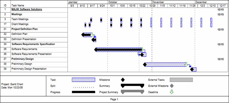
Gantt Chart - A chart that displays progress over time, in this case used to keep track of a project.
Linear Sequential Model / Classic Waterfall Model – A systematic, sequential approach to software development that progresses from this Software Plan to Requirement Specifications, Preliminary/Detailed, and finally Acceptance Tests.
MAC address - Media Access Control address, given to a device in a network. It
consists of a 48-bit hexadecimal number (12 characters). The address is
normally assigned to a device, such as a network card, when it is manufactured.
Network Device - A computer, peripheral or other related
communications equipment attached to a network.
Prototype – A rudimentary depiction of the design of the final product.
Virtual - Something which is a representation rather than the ‘real’ thing, thus
‘virtual reality’.