Detailed Design
Requested by: Mr. Eric
Crossman
Assistant Systems & Operations Manager
Siena College
School of Science
Mr. Ken
Swarner
Systems & Operations Manager
Siena College
School of Science
Virtual
Network Device Mapping System
Prepared by:
MAJIK Software Solutions
Amanda
Danko
Kevin
Johnson
Ian
Kost
Mark
Riley
March 6, 2007
Table of Contents
-Detailed Design-
Introduction. 3
Section
1: External Design Specifications. 3
1.1
User Displays. 3
1.2
Data Flow Diagrams. 16
1.3
Logical Data Dictionary. 24
1.4
Logical Data Stores. 27
1.5
Entity-Relationship Diagram.. 29
1.6
Physical Data Structures and Data File Specification. 30
Section
2: Architectural Design Specification. 31
2.1
Structure Diagram.. 31
2.2
Use Cases. 33
2.3
Functional Requirements. 33
2.4
Development Environment Information. 40
Section
3: Detailed Design Specification. 41
3.1
Documentation Prologue for each Routine. 41
3.1.1 login. 41
3.1.2 logout 41
3.1.3 displayRoom.. 41
3.1.4 displayDevice. 41
3.1.5 displayRoom_Notes. 41
3.1.6 displayDevice_Info. 41
3.1.7 search. 42
3.1.8 editPassword. 42
3.1.9 editPermissions. 42
3.1.10 editRoom_Notes. 42
3.2
Pseudocode for each Routine. 43
3.2.1 login. 43
3.2.2 logout 43
3.2.3 displayRoom.. 43
3.2.4 displayDevice. 43
3.2.5 displayRoom_Notes. 43
3.2.6 displayDevice_Info. 44
3.2.7 search. 44
3.2.8 editPassword. 44
3.2.9 editPermissions. 44
3.2.10 editRoom_Notes. 44
Section
4: Testing Requirements. 45
4.1
Test Plan. 45
4.2
Unit Test 49
4.3
Integration Test 80
4.4
Acceptance Test 81
Section
5: Appendices. 87
5.1
Gantt Chart 87
5.2
Glossary of Terms. 88
The Virtual Network Device Mapping System is being developed
at the request of Mr. Eric Crossman and Mr. Ken Swarner. The system will allow
for a web-based, graphical organization and easy access to information about
the devices on the network in the School
of Science at Siena
College located in Roger Bacon and the
Morrell Science Center.
This document outlines the detailed design of our solution system.
Login Screen:
This is the first page that all users see when accessing the
program. It gives a short description of the purpose of the program, followed
by the login dialogue. This page also links to the websites of Team MAJIK via
the team logo link, Siena
College, the Computer
Science Department, and the Software Engineering course. It is the same for all
users.
Failed Login:
If a user enters an incorrect User Name and/or an incorrect
Password, they are presented with a message informing them of their error.
Logged In:
This is the first page a user will see after logging in. On
this page, and all others after it, they will have the option to logout. They
can do this by clicking the link in the top right hand corner of the page. This
area also displays the User Name that they are logged into. Administrative
users will see the Control Panel link as displayed, and all other users will
not. Otherwise, the page displays the same for all users. Additionally, the
page gives directions for use of the program and the option of choosing a floor
to view or using the Search feature.
Floor Plan:
The Floor Plan page indicates the building and floor
currently displayed. For the purposes of this prototype it is Roger Bacon Hall,
third floor. Immediately below, the physical layout of that floor is
graphically displayed. Users can select individual rooms in order to be brought
to a closer view. On this, and subsequent pages, there are dropdown menus at
the top allowing users to quickly move to different floors in the two
buildings. There is also a link to the Search page present.
Room Layout:
The Room Layout page gives a close-up view of an individual
room. It displays the location of all network devices in the room graphically.
The devices are displayed as symbols which are defined in a legend to the left
of the Room Layout image. Each device can be selected by a user, causing
information pertaining to that device to be displayed in a dialogue box at the
bottom of the page. The Room Notes that an Administrator user has saved for the
room through use of the Control Panel are displayed on the right side. Also, a
link is displayed allowing a user to quickly zoom out to the Floor Plan they
were viewing before selecting that room.
Detailed Device Information:
The Room Layout image shows the device info partially
abbreviated. This image shows off all information fields possible for a network
device. The values given are meant as examples and may not follow the exact
format of real data.
Search:
Devices can be searched for using any of the categories of
information stored. Although all of the categories are displayed, only one is
required to perform a search. Any categories filled in will be factored into
the search, and those left blank will not be utilized. This is meant to give
the greatest amount of flexibility possible in finding a device.
Search Results:
Search results are displayed with abbreviated information.
The Device Name, Building, Room, IP address, MAC address, and Equipment Type of
each device matching the search criteria are displayed. Selecting the Device
Name will display the Room Layout view of the room that the device is located
in, with the full device information in the dialog box below the layout.
Multiple results are displayed one below the other.
Control Panel:
This page contains a menu detailing Administrative tasks. It
can only be accessed by an Administrative user. Three Control Panel options are
displayed; the ability to change passwords, edit permissions, and add room
notes. Below each menu option is a short description and brief directions.
Selecting a Control Panel menu item will load a new page.
Passwords:
The User Name is selected from a dropdown menu, and a new
password is entered. The change is complete when the “Confirm” button is
selected. A new page is loaded displaying a confirmation message. That page is
displayed below.
Password Change Confirmation:
Permissions Device Search:
Allows limitation of what network devices individual users
can view. The Administrator first searches for devices according to Building,
Room, Device Name, or Equipment Type. Generally, the Administrator will be
searching for a group of devices. After entering the proper search criteria,
the “Search” button is selected and a new page is loaded.
Permissions Selection:
On the left, the search results are displayed. Devices can
be chosen via a checkbox on each result. Once the devices are selected, the
Administrator can choose a user from the dropdown menu on the right and set the
user's permission for those devices to either "Read" or
"Restrict." Read will allow the user to see that device and all
information regarding it, and Restrict will prevent the user from viewing any
information about the device. After the "Confirm" button is selected,
the original Permissions page is displayed.
Room Notes:
Notes pertaining to specific rooms can be saved here. They
will be displayed for all users on the Room Layout screen. The Administrator
first selects a building, and a floor within that building. Then, they enter
the number of the room they wish to save a note about. Finally, the
Administrator types in whatever notes they want saved about the room and
selects “Save.” The Room Notes Confirmation page is displayed.
Room Notes Confirmation:
Legend for icons used in the Data Flow Diagrams.
Context Diagram: It is the most basic diagram that
shows the interaction between the user and the system.
Level 0 Diagram:
This is an expansion of the “Virtual Device Network Mapping System” that
was shown in the Context Diagram.
The Select
Item from Control Panel diagram is a Level 1 Diagram. It shows the processes an Administrator can
perform.
Manage User Request: This is a Level 2 diagram that
shows the processes for all the different users.
Floor Plan/Permissions Screen: This is shows the process of selecting a room
after a floor has been selected.
Room Select Screen:
This shows the processes of selecting a device for information or going
back to a higher level of display.
Faculty-Room-Page
Locations:
Level 2.1.1 Destination: Faculty User
Source:
User and Network Device Information Database
Administrator-Room-Page
Locations:
Level 2.1.1 Destination: Administrator
User
Source:
User and Network Device Information Database
Special-Room-Page
Locations:
Level 2.1.1 Destination: Special User
Source:
User and Network Device Information Database
Admin-Login-Page
Locations:
Level 0 Destination: Administrator
Source:
Request Login
Faculty-Login-Page
Locations:
Level 0 Destination: Faculty
Source:
Request Login
Special-Login-Page
Locations:
Level 0 Destination: Special User
Source:
Request Login
Special-Page
Locations:
Level 0 Destination: Special User
Source:
Manage User Request
Level 2.1 Destination: Special User
Source:
Select Floor Plan Screen
Faculty-Page
Locations:
Level 0 Destination: Faculty
Source:
Manage User Request
Level 2.1 Destination: Faculty
Source:
Select Floor Plan Screen
Administrator-Page
Locations:
Level 0 Destination: Administrator
Source:
Manage User Request
Level 2.1 Destination: Administrator
Source:
Select Floor Plan Screen
Control-Panel-Page
Locations:
Level 0 Destination: Administrator
Source:
Select Item from Control Panel
Level 1.1 Destination: Administrator
Source:
Click Control Panel Button
Level 2.1 Destination: Administrator
Source:
Select Item from Control Panel
System-Data
Locations:
Level 0 Destination: Manage User Request
Source:
User and Network Device Information Database
Level 2.1 Destination: Select Floor
Plan Screen Source: User and Network Device
Information Database
Level 2.1 Destination: Request
Search Source: User and Network Device
Information Database
Logout-Page
Locations:
Level 2.1 Destination: Administrator
Destination:
Faculty
Destination:
Special User
Source:
Request-Logout
Search-Data
Locations:
Level 2.1 Destination: Administrator
Destination:
Faculty
Destination:
Special User
Source:
Request Search
Device-Data
Locations:
Level
2.1.1.1 Destination:
Administrator
Destination:
Faculty
Destination:
Special User
Source:
View Device Info
Retreived-Info
Locations:
Level
2.1.1.1 Destination: View
Device Info
Source:
User and Network Device Information Database
Password-Page
Locations:
Level 1.1 Destination: Administrator
Source: Edit Password
Permissions-Page
Locations:
Level 1.1 Destination: Administrator
Source:
Edit Permissions
Room-Notes-Page
Locations:
Level 1.1 Destination: Administrator
Source:
Edit Room Notes
Page
Locations:
Level 1.1 Destination: Administrator
Source:
Edit Wall boxes
Password-Data
Locations:
Level 1.1 Destination: Edit Password
Source:
User and Network Device Information Database
Permissions-Data
Locations:
Level 1.1 Destination: Edit
Permissions
Source:
User and Network Device Information Database
Room-Note-Data
Locations:
Level 1.1 Destination: Edit Room
Note
Source:
User and Network Device Information Database
Wall box-Data
Locations:
Level 1.1 Destination: Edit Wall box
Source:
User and Network Device Information Database
The following information presents a preliminary description
of the data stored in the Virtual Network Device Mapping System database. The
data is presented in a layout of the table structure. Primary Keys are
underlined.
Table: User
Fields:
Lname: CHAR(12)
-User's last name
Fname:
CHAR(12)
-User's first name
Building:
CHAR(3)
-name of the building which the user's office or room is located
Room_Num:
VARCHAR(5)
-number of the room which the user's office or room is located
login:
CHAR(8)
- name given to the user to login under
Password:
CHAR(8)
-Password
for the login, created by the user
User_type:
CHAR(8)
- which class of user a login is classified as (used to specify permissions)
Table: Room
Fields:
Num:
VARCHAR(5)
-
The room number
Building:
CHAR(3)
-
The building the room is found in
Department:
CHAR(15)
-
The department the room is used by
Type:
CHAR(10)
-
The type of room; i.e. lecture, lab, etc...
EEC:
CHAR(1)
-
Indicates if the room is an Electronically Enhanced Classroom - Y/N
Table: Machine
Fields:
Id:
INTEGER
-
A unique identifier
Host_Name:
VARCHAR(30)
-
The hostname of the machine
IP_Address:
VARCHAR(15)
-
The IP Address of the machine
MAC_Address:
VARCHAR(20)
-
The MAC Address of the machine
Asset_Tag:
INTEGER
-
The IT&S Asset Tag value
Serial_Num:
VARCHAR(20)
-
The machine's serial number
Department:
CHAR(15)
-
The department to which the machine belongs (the sub-network)
Building:
CHAR(3)
-
The building in which the machine is located
Room:
VARCHAR(5)
-
The room in which the machine is located
CPU:
VARCHAR(6)
-
The CPU type
Speed:
VARCHAR(6)
-
The speed of the processor
Disk:
VARCHAR(5)
-
The disk size
Memory:
VARCHAR(5)
-
The memory size
User:
CHAR(12)
-
The name of the primary user
User_Type:
CHAR(15)
-
The type of primary user; i.e. student, faculty, etc...
Priority:
CHAR(1)
-
Priority level; L-low; M- medium; H-High
PO_Num:
VARCHAR(15)
-
Purchase order number
VP_Code:
CHAR(4)
-
Always VPAA for Vice President of Academic Affairs
Manufacturer:
CHAR(15)
-
The name of the manufacturing company
Model:
VARCHAR(15)
-
The model number of the machine
Equipment_Type:
CHAR(20)
-
The type of equipment; i.e. PC, Mac, Laptop, Wireless Access Point, etc.
Monitor_Type:
CHAR(5)
-
The type of monitor; i.e. LCD, CRT
Purchase_Year:
DATE
-
The date the machine/equipment was purchased
Installed_Date:
DATE
-
The date the machine/equipment was installed
X_coord:
VARCHAR(3)
-
The X coordinate of the location of the machine/equipment in the room
Y_coord:
VARCHAR(3)
-
The Y coordinate of the location of the machine/equipment in the room
Comments:
VARCHAR(100)
-
Comments about the machine/equipment
The user table is populated with names of users, set by the
administrator, and is updated by the administrator
User
The machine and room tables are populated with information
given to us by the clients, and updates will be pushed to these tables by the
clients.
Machine
Room
A
Module represents an instruction that carries out an operation.
A
Library Module behaves in the same manner every time that it is called
upon.
The Virtual
Network Device Mapping System will service three users.
The
Administrator user will have full access to all features of the software,
including the ability to view and edit all information regarding each device on
the network. The Administrator user will manage all other user accounts.
A
Faculty/Staff user will only have the option to view information about devices
pertaining to them (i.e. their office and/or classrooms, etc.). The Faculty/Staff user will have no editing
capability.
The Special
user's use of the system will vary. The
Special user will be granted use of certain features of the system by the
administrator as needed, including extended view of information about devices
and possible editing capabilities.
The
following list outlines the required functionality to be included in the final
solution. The requirements are listed
according to user case and then by screens the user will view.
General:
The Virtual Network Device Mapping System is web-based.
Administrator User:
The Administrator user will have an account.
The Administrator user will have a username and password.
The Administrator will establish usernames and passwords for
other users.
Login Screen:
The user will log in with correct username and password.
An incorrect login will provide an appropriate error
message.
Welcome Screen:
The user will have access to a control panel on the welcome
screen.
The user will be able to perform a search for certain
devices or a specific device based on indicated search criteria.
The user will be able to select a floor of Roger Bacon Hall
from a menu to view a floor plan layout.
The user will be able to select a floor of Morrell Science
Center from a menu to
view a floor plan layout.
The user will be able to logout from the welcome screen by
clicking the "Logout" link.
Control Panel Index Screen:
The user will be able to change user passwords in the
control panel.
The user will be able to change user permissions for devices
in the control panel.
The user will be able to insert notes pertaining to a
specific room or devices within a room.
The user will be able to log out from the control panel
index screen.
User Control Panel Screen:
The Administrator user will be able to choose a user for
which the password is to be changed.
The Administrator will enter a new password for the chosen
user.
The Administrator will submit changes.
A message will appear indicating a that a change has been
accepted.
The Administrator user will be able to log out from the user
control panel screen.
User Permissions Control Panel Screen:
The Administrator will be able to choose a user for which
the permissions are to be set.
The Administrator will be able to search for or choose a
device or set of devices for which the user’s permissions are to apply to.
The Administrator will be able to choose the permission
level for the user with reference to the chosen device(s): read or restrict.
The Administrator will submit the changes.
A message will appear indicating that a change has been
accepted.
The Administrator user will be able to log out from the user
permissions control panel screen.
Room Notes Control Panel Screen:
The Administrator user will be able to choose a building and
floor for which the room is in.
The Administrator will be able to enter a room number for
which to add notes.
The Administrator will be able to add notes into a text box
for the chosen room.
The Administrator will submit the changes.
A message will appear indicating that a change has been
accepted.
The Administrator user will be able to log out from the room
notes control panel screen.
Floor Plan Screen:
A floor plan for the chosen floor will be displayed on the
screen.
The building name and floor number will be displayed on the
screen.
The Administrator user will be able to access the control
panel from this screen.
Administrator user will be able to view information about
all rooms and devices on the floor.
The Administrator will be able to choose a room from the
floor plan to view a detailed room layout.
The Administrator user will be able to log out from the
floor plan screen.
The Administrator user will be able to choose a different
floor of either Roger Bacon Hall or Morrell
Science Center
from a drop down menu.
Room Layout Screen:
A room layout will be displayed for the selected room.
The existence and location of devices within the room will
be indicated in the layout.
The building name, floor number, and room number will be
displayed on the screen.
The Administrative user will be able to zoom out to the
floor level diagram to which the room belongs.
The Administrator user will be able to choose a device
within the room to view the information pertaining to that device.
The information for a specific device will appear below the
room layout in a text box.
Any available notes for the selected room will be displayed
on the screen for easy reference.
A legend will be displayed below the layout to denote the
meaning of symbols in the layout.
The Administrator user will be able to log out from the room
layout screen.
Search Screen:
The Administrator user will be able to search for a device
on the following criteria:
Asset Tag
Number
Priority
User
User Type
Department
VP Code
Building
Room
Manufacturer
Model
Equipment
Type
Monitor
Type
Purchase
Year
Installed
Date
Purchase
Order Number
CPU
Speed
Disk
Memory
MAC Address
Serial
Number
Summarized search results will be displayed on the same
screen.
Search results will be selectable to view more detailed
results.
When selected, detailed search results will be displayed in
the room layout view.
Faculty/Staff User:
The Faculty/Staff user will have an account established by
the Administrator.
The Faculty/Staff user will have a username and password.
Login Screen:
The user will log in with correct username and password.
An incorrect login will provide an appropriate error
message.
Welcome Screen:
The user will be able to perform a search for certain
devices or a specific device based on indicated search criteria.
The user will be able to select a floor of Roger Bacon Hall
from a menu to view a floor plan layout.
The user will be able to select a floor of Morrell Science
Center from a menu to
view a floor plan layout.
The user will be able to logout from the welcome screen by
clicking the "Logout" link.
Floor Plan Screen:
A floor plan for the chosen floor will be displayed on the
screen.
The building name and floor number will be displayed on the
screen.
Faculty/Staff user will be able to view information about
limited rooms and devices on the floor.
Rooms available for viewing will be highlighted so a
Faculty/Staff user is aware of which rooms can be selected.
The Faculty/Staff will be able to choose a room from the
floor plan to view a detailed room layout.
The Faculty/Staff user will be able to log out from the
floor plan screen.
The Faculty/Staff user will be able to choose a different
floor of either Roger Bacon Hall or Morrell
Science Center
from a drop down menu.
Room Layout Screen:
A room layout will be displayed for the selected room.
The existence and location of devices within the room that
will be indicated in the layout.
The building name, floor number, and room number will be
displayed on the screen.
The Faculty/Staff user will be able to zoom out to the floor
level diagram to which the room belongs.
The Faculty/Staff user will be able to choose certain
devices within the room to view the information pertaining to that device.
The information for a specific device will appear below the
room layout in a text box.
Any available notes for the selected room will be displayed
on the screen for easy reference.
A legend will be displayed below the layout to denote the
meaning of symbols in the layout.
The Faculty/Staff user will be able to log out from the room
layout screen.
Search Screen:
The Faculty/Staff user will be able to do a search for a
device on the following criteria:
Asset Tag
Number
Priority
User
User Type
Department
VP Code
Building
Room
Manufacturer
Model
Equipment
Type
Monitor
Type
Purchase
Year
Installed
Date
Purchase
Order Number
CPU
Speed
Disk
Memory
MAC Address
Serial
Number
Search results will be limited to what the user has
permissions to view.
Summarized search results will be displayed on the same
screen.
Search results will be selectable to view more detailed
results.
When selected, detailed search results will be displayed in
the room layout view.
Special User:
The Special user will have an account established by the
Administrator.
The Special user will have a username and password.
The Special user will have access to any feature the
Administrator user grants them, up to and including administrative functions.
The machines we will be using to do our development work,
and their specifications, as well as the software that we will be using to
develop our programs are listed here.
Server:
Oracle, version 10g
Mysql, version 4.1.14
PHP, version 4.3.11
Apache, version 2.0.46
Browser Environment:
Microsoft Internet Explorer version 6.0.2800.1106
Mozilla Firefox version 1.0 preview release
Mozilla Firefox version 1.0
Apple Safari 1.2
Software:
Adobe Acrobat version 5.0.5
Adobe Reader version 6.0.0
Microsoft Office Word 2000 9.0.4402
Microsoft Office PowerPoint 2000 SR1 9.0.3821
WinSCP version 3.1.0 (Build 165)
Putty Release 0.53b
Macromedia Dreamweaver MX Education Edition 6.0
Macromedia Fireworks MX Education Edition 6.0
Visible Analyst Education Edition version 7.5.5
Microsoft Project 2000 9.0.2001.0219SR1
Microsoft Windows 2000 5.00.2195 Service Pack 3
Microsoft Windows XP Professional Version 2002 Service Pack
2
Systems:
Dell Dimension Dim4550
Intel Pentium 4 2.40 GHz
512 MB of RAM
Macintosh iMac
2.0GHz Intel Core 2 Duo
1GB of RAM
3.1.1 login
This routine takes a user name
and a password as input from the user.
It connects to the database and verifies the information. If the information is verified it allows
access to the rest of the program. Otherwise, an error message is displayed to
the screen.
This
routine severs the connection to the database and redirects to the index page.
This routine takes as input the
room selected on the Floor Plan page. It
displays the floor and room numbers in the heading, and the image for that
room.
This routine displays the icon
for a device in the correct location within the Room Layout image.
This routine takes as input the
selected room number. It retrieves the
Room Notes information for that room from the database and displays it to the
page.
This routine displays the device
information for a selected device in the correct area of the page.
This routine takes as input the
information entered into search fields. It returns all devices which match the
entered criteria.
This
routine changes the password stored in the database for the selected user.
This routine takes as input a
user and one or more selected devices, and sets a flag that determines whether
that user can view the information for the selected device(s).
This
routine stores entered text into the database for the selected room.
connect to
database
if( info is
verified )
create
Session
load
‘Logged In’ page
else
disconnect
from database
output
error message
end Session
disconnect
from database
load ‘Log
In’ page
room_number
= input from user
output(
building_name “ – “ floor_number “ – Room #” room_number )
room_layout_image =
image_array[room_number]
device =
input from user
lookup
device_type
lookup
device_coords
output( image.device_type ) at location device_coords
room_number = input from user
if( room_number.notes == NULL )
output(
“n/a” )
else
output(
room_number.notes )
device =
user input
output(
device.* )
search_vars[n]
= user input from search fields
x = 0
for( i=1 to
n) || n = # of devices
{
compare
device to search criteria
if
( device matches search criteria )
{
output( device_name, building,
room, ip_address, mac_address, equip_type )
output( newline “------“ newline )
x++
}
}
if( x==0 )
output(
“No results found.” )
user_name =
user input
password =
user input
user_name.pass
= password
user_name =
user input
devices[n]
= user selects devices
bool
permission = user input || True – read,
False – restrict
for ( i=1
to n)
devices[i].perm
= permission
room_number = input from user
room_note = input string from
user
room_number.notes = room_note
To test the system, we will perform four testing
stages. The first is unit testing where
each component is tested individually for errors. The second stage is integration testing where
we will ensure that components interact correctly to perform higher
functions. System testing, the third
stage, involves ensuring that all the features of the system meet the
functional requirements previously defined in the Requirements Specification. Finally, acceptance testing will be carried
out to ensure that the delivered system meets all of the requirements as
specified by our clients.
4.1.1 Test Plan Identifier:
Virtual Network
Device Mapping System Test Plan version 1.1
4.1.2
Introduction
In order to ensure the highest quality product possible, and
to be sure that our program adequately meets the needs of our clients, we are
utilizing four separate types of testing.
First, we will implement Unit Tests to ensure that each module is
functioning correctly, including individual test cases. Second, we will perform Integration Tests to
be sure that each module is interacting correctly with other modules to perform
high level tasks. If changes are made to
interdependent modules, Regression Testing will be done as a part of Integration
Tests. Third, we will perform a System
Test, which verifies that all functional requirements have been met and are
operating as defined in the Requirements Specification. Fourth, Acceptance Testing will be carried
out to ensure that the delivered system meets all of the requirements as
specified by our clients.
4.1.3
Test Items
We will be running our software on a Dell 2550 Server
running Red Hat Linux – ES Release 3, with Oracle version 10g, PHP version
4.3.11 and the Apache web server version 2.0.46. Our software will be tested to ensure
compatibility with Microsoft Internet Explorer version 6.0, Mozilla Firefox
version 1.0, and Apple Safari version 1.2.
Also, our software will be designed to be viewed on a monitor set to
1024x768 resolution.
4.1.4 Features Not To Be Tested
It is our plan to test all parts of the project that we have
implemented. This does not include the
way in which network device information is entered into the database, or the
ways in which that data can be edited.
4.1.5 Approach
We have designated two members of our team to specialize in
testing. As modules are completed, we
will perform our Unit Tests on them.
Following that, Integration Testing will occur. When these have been successfully completed,
the System Test will be executed.
Finally, we will perform the Acceptance Test.
4.1.6 Pass/Fail Criteria
Each Test Case will Pass if it consistently meets all
requirements specified in the Unit Test.
If a Test Case fails to produce the required results, it will Fail. Criteria used to determine whether a Test
Case is passed or failed include:
- Task performs action specified.
- Task performs action in a
reasonable amount of time.
- Task performed without errors.
- Task displays output correctly.
- Individual
test cases for each GUI will include tests on all links, buttons, text
boxes, drop-down menus and any other means of user input in that
interface.
- Master
Test Plan – The master test plan will be passed if and only if all lower
level test plans (Unit Tests) are completed and passed. Any lower level plan that fails will
result in a new version of that module which will then be subjected to the
original Unit Test. Regression Testing
will also be implemented in this case.
4.1.7 Suspension Criteria and Resumption Requirements
Testing activity will be suspended under the following
circumstances:
- System
failure.
- Excessive
Test Case failures.
- Changes
made to the Unit being tested.
- A
need for Regression Testing to begin which involves the unit being tested.
Testing will resume from the beginning of the Unit Test when
it is believed that the problems causing failure have been resolved.
4.1.8 Test Deliverables
The test
deliverables include a complete documentation of the Unit Tests and the
Integration Tests. A fully completed
checklist of the Functional Requirements and the Acceptance Test will also be
delivered.
4.1.9 Testing Tasks
The Testing Tasks
will be comprised of Unit Tests for each screen that the user will be able to
navigate through. There are 3 different
types of users and some tests are specific to a certain user. The screens that will be tested that are
common to all users are the login page, view floor plan and view office
layout. The administrative user will
have access to another page called the control panel page. Each of these pages will be tested in a
logical order allowing for quick results.
4.1.10 Environmental Needs
-Oracle, version
10g
-Mysql, version
4.1.14
-PHP, version
4.3.11
-Apache, version
2.0.46
-Browsers:
-Microsoft
Internet Explorer version 6.0.2800.1106
-Mozilla
Firefox version 1.0 preview release
-Mozilla
Firefox version 1.0
-Apple Safari
1.2
-Microsoft Windows
2000 5.00.2195 Service Pack 3
-Microsoft Windows
XP Professional Version 2002 Service Pack 2
4.1.11 Responsibilities
- Amanda
Danko is the Team Leader. She will make sure that all required testing is
in place and that all features are tested.
- Mark
Riley will be the head tester. He
will be in charge of providing the overall strategy for testing.
4.1.12 Staffing and Training Needs
- Mark
Riley is in charge of testing and making crucial decisions that will
affect what is tested and how it is tested.
- Mark
will also work with Amanda Danko in each stage of testing for our
software.
4.1.13 Schedule
Scheduled
Milestones:
-April 30,
2007: Acceptance Test Deliverables due
-May 1, 2007: Acceptance Test Presentations
-May 4, 2007: Academic Celebration Presentations
4.1.14 Risks and Contingencies
The current status
of the project has rendered us unable to anticipate the possible risks and
therefore their countermeasures. As the
development process continues, we will be able to further assess the possible
risks we may encounter.
4.1.15 Approvals
Names and Titles for Approval:
Amanda Danko - MAJIK
Software Solutions Team Leader
Kevin Johnson –
MAJIK Software Solutions Lead Developer
Ian Kost – MAJIK
Software Solutions Developer
Mark Riley – MAJIK
Software Solutions Lead Tester
Mr. Eric Crossman
- Assistant Systems Administrator
Mr. Ken Swarner -
Systems Administrator
|
MAJIK
Software Solutions
|
|
Virtual
Network Device Mapping System
|
|
|
|
|
|
Unit Test
Catalog
|
|
Test Result
|
Test Number
|
Unit Test Name
|
|
P
F
|
1
|
Login
Screen
|
|
P
F
|
2
|
Administrator
Welcome Screen
|
|
P
F
|
3
|
Faculty/Staff
Welcome Screen
|
|
P
F
|
4
|
Roger
Bacon Floor 1 Layout Screen
|
|
P
F
|
5
|
Roger
Bacon Floor 2 Layout Screen
|
|
P
F
|
6
|
Roger
Bacon Floor 3 Layout Screen
|
|
P
F
|
7
|
Roger
Bacon Floor 4 Layout Screen
|
|
P
F
|
8
|
Morrell Science
Center Floor 1 Layout Screen
|
|
P
F
|
9
|
Morrell Science
Center Floor 2 Layout Screen
|
|
P
F
|
10
|
Morrell Science
Center Floor 3 Layout Screen
|
|
P
F
|
11
|
Room View
Screen
|
|
P
F
|
12
|
Administrator
Control Panel Index Screen
|
|
P
F
|
13
|
Manage
Users Control Panel Screen
|
|
P
F
|
14
|
Permissions
Control Panel Screen
|
|
P
F
|
15
|
Room
Notes Control Panel Screen
|
|
P
F
|
16
|
Search
Screen
|
|
|
|
|
|
|
|
|
|
P = Pass
|
|
|
|
F = Fail
|
|
|
|
MAJIK Software Solutions
|
|
|
|
|
|
Virtual Network Device Mapping System
|
|
|
|
|
|
|
|
|
|
|
|
|
|
Test Number 1 - Login Screen Test Cases
|
|
|
|
|
|
|
|
|
|
|
|
|
Number
|
Test Case Name
|
Description
|
Input
|
Expected Result
|
Actual Result/Comments
|
TestResult (Pass/Fail)
|
|
1.1
|
Index Page Loads
|
Correct page load.
|
N/A
|
Index page loads and all components are displayed on the screen.
|
|
|
|
1.2
|
Correct Login - Administrator
|
Log in with valid administrator account and password.
|
Administrator username and password
|
Welcome screen for administrators loads.
|
|
|
|
1.3
|
Correct Login - Faculty/Staff
|
Log in with valid faculty/staff account and password
|
Faculty/Staff username and password
|
Welcome screen for faculty/staff loads.
|
|
|
|
1.4
|
Incorrect Username Login
|
Login with invalid username.
|
Username
|
Message generated indicating invalid username.
|
|
|
|
1.5
|
Incorrect Password Login
|
Log in with invalid password.
|
Password
|
Message generated indicating invalid password.
|
|
|
|
1.6
|
Login with Empty Fields
|
Login with username and password fields empty.
|
N/A
|
Message generated indicating invalid username or password.
|
|
|
|
1.7
|
Click Clear Button
|
User clicks clear button.
|
N/A
|
Username and password field are cleared of contents.
|
|
|
|
1.8
|
Click Link to MAJIK Website
|
User clicks link to the MAJIK website.
|
N/A
|
MAJIK Team website loads.
|
|
|
|
1.9
|
Click Link to Software Engineering Website
|
User clicks link to the Software Engineering website.
|
N/A
|
Software Engineering website loads.
|
|
|
|
|
|
|
|
|
Summary of Tests for this Unit
|
P
|
|
|
|
|
|
|
|
|
|
MAJIK Software Solutions
|
|
|
|
|
|
Virtual
Network Device Mapping System
|
|
|
|
|
|
|
|
|
|
|
|
|
|
Test
Number 2 - Administrator Welcome Screen Test Cases
|
|
|
|
|
|
|
|
|
|
|
|
Number
|
Test Case Name
|
Description
|
Input
|
Expected Result
|
Actual Result/Comments
|
TestResult (Pass/Fail)
|
|
2.1
|
Welcome
page loads.
|
Page
loads correctly.
|
N/A
|
Page
loads and all components are displayed on the screen.
|
|
|
|
2.2
|
Click
Control Panel Button.
|
User
clicks the Control Panel button.
|
N/A
|
The
control panel screen loads.
|
|
|
|
2.3
|
Click
logout button.
|
User
clicks the Logout button.
|
N/A
|
The user
is logged out of the system and returns to the login screen.
|
|
|
|
2.4
|
Click the
Roger Bacon Hall 1st Floor link.
|
A link to
the layout of the first floor of Roger Bacon Hall.
|
N/A
|
A new
page loads displaying the floor plan layout of the first floor of Roger Bacon
Hall.
|
|
|
|
2.5
|
Click the
Roger Bacon Hall 2nd Floor link.
|
A link to
the layout of the second floor of Roger Bacon Hall.
|
N/A
|
A new
page loads displaying the floor plan layout of the second floor of Roger
Bacon Hall.
|
|
|
|
2.6
|
Click the
Roger Bacon Hall 3rd Floor link.
|
A link to
the layout of the third floor of Roger Bacon Hall.
|
N/A
|
A new
page loads displaying the floor plan layout of the third floor of Roger Bacon
Hall.
|
|
|
|
2.7
|
Click the
Roger Bacon Hall 4th Floor link.
|
A link to
the layout of the fourth floor of Roger Bacon Hall.
|
N/A
|
A new
page loads displaying the floor plan layout of the fourth floor of Roger
Bacon Hall.
|
|
|
|
2.8
|
Click the
Morell Science Center
1st Floor Link
|
A link to
the layout of the first floor of Morrell
Science Center.
|
N/A
|
A new
page loads displaying the floor plan layout of the first floor of Morrell Science Center.
|
|
|
|
2.9
|
Click the
Morell Science Center
2nd Floor Link
|
A link to
the layout of the second floor of Morrell
Science Center.
|
N/A
|
A new page
loads displaying the floor plan layout of the second floor of Morrell Science Center.
|
|
|
|
2.10
|
Click the
Morell Science Center
3rd Floor Link
|
A link to
the layout of the third floor of Morrell
Science Center.
|
N/A
|
A new
page loads displaying the floor plan layout of the third floor of Morrell Science Center.
|
|
|
|
|
|
|
|
|
Summary
of Tests for this Unit
|
P
|
|
|
Back to Catalog
|
|
|
|
|
|
|
MAJIK
Software Solutions
|
|
|
|
|
|
Virtual
Network Device Mapping System
|
|
|
|
|
|
|
|
|
|
|
|
|
|
Test
Number 3 - Faculty/Staff Welcome Screen Test Cases
|
|
|
|
|
|
|
|
|
|
|
|
Number
|
Test Case Name
|
Description
|
Input
|
Expected Result
|
Actual Result/Comments
|
TestResult (Pass/Fail)
|
|
3.1
|
Welcome
page loads.
|
Page
loads correctly.
|
N/A
|
Page
loads and all components are displayed on the screen.
|
|
|
|
3.2
|
Click
logout button.
|
A link to
logout of the system.
|
N/A
|
The user
is logged out of the system and is returned to the login screen.
|
|
|
|
3.3
|
Click the
Roger Bacon Hall 1st Floor link.
|
A link to
the layout of the first floor of Roger Bacon Hall.
|
N/A
|
A new
page loads displaying the floor plan layout of the first floor of Roger Bacon
Hall.
|
|
|
|
3.4
|
Click the
Roger Bacon Hall 2nd Floor link.
|
A link to
the layout of the second floor of Roger Bacon Hall.
|
N/A
|
A new
page loads displaying the floor plan layout of the second floor of Roger
Bacon Hall.
|
|
|
|
3.5
|
Click the
Roger Bacon Hall 3rd Floor link.
|
A link to
the layout of the third floor of Roger Bacon Hall.
|
N/A
|
A new
page loads displaying the floor plan layout of the third floor of Roger Bacon
Hall.
|
|
|
|
3.6
|
Click the
Roger Bacon Hall 4th Floor link.
|
A link to
the layout of the fourth floor of Roger Bacon Hall.
|
N/A
|
A new
page loads displaying the floor plan layout of the fourth floor of Roger
Bacon Hall.
|
|
|
|
3.7
|
Click the
Morell Science Center
1st Floor Link
|
A link to
the layout of the first floor of Morrell
Science Center.
|
N/A
|
A new
page loads displaying the floor plan layout of the first floor of Morrell Science Center.
|
|
|
|
3.8
|
Click the
Morell Science Center
2nd Floor Link
|
A link to
the layout of the second floor of Morrell
Science Center.
|
N/A
|
A new
page loads displaying the floor plan layout of the second floor of Morrell Science Center.
|
|
|
|
3.9
|
Click the
Morell Science Center
3rd Floor Link
|
A link to
the layout of the third floor of Morrell
Science Center.
|
N/A
|
A new
page loads displaying the floor plan layout of the third floor of Morrell Science Center.
|
|
|
|
|
|
|
|
|
Summary
of Tests for this Unit
|
P
|
|
|
Back to Catalog
|
|
|
|
|
|
|
MAJIK
Software Solutions
|
|
|
|
|
|
Virtual
Network Device Mapping System
|
|
|
|
|
|
|
|
|
|
|
|
|
|
Test
Number 4 - Roger Bacon Floor 1 Layout Screen
|
|
|
|
|
|
|
|
|
|
|
|
|
Number
|
Test Case Name
|
Description
|
Input
|
Expected Result
|
Actual Result/Comments
|
TestResult (Pass/Fail)
|
|
4.1
|
Layout
Screen loads.
|
Page
loads correctly.
|
N/A
|
Page
loads and all components are displayed on the screen.
|
|
|
|
4.2
|
Select
Roger Bacon Floor 1 and Press Go
|
A link to
the layout of the first floor of Roger Bacon Hall.
|
N/A
|
A new
page loads displaying the floor plan layout of the first floor of Roger Bacon
Hall.
|
|
|
|
4.3
|
Select
Roger Bacon Floor 2 and Press Go
|
A link to
the layout of the second floor of Roger Bacon Hall.
|
N/A
|
A new
page loads displaying the floor plan layout of the first floor of Roger Bacon
Hall.
|
|
|
|
4.4
|
Select
Roger Bacon Floor 3 and Press Go
|
A link to
the layout of the third floor of Roger Bacon Hall.
|
N/A
|
A new
page loads displaying the floor plan layout of the second floor of Roger
Bacon Hall.
|
|
|
|
4.5
|
Select
Roger Bacon Floor 4 and Press Go
|
A link to
the layout of the fourth floor of Roger Bacon Hall.
|
N/A
|
A new
page loads displaying the floor plan layout of the third floor of Roger Bacon
Hall.
|
|
|
|
4.6
|
Select Morell
Science Center Floor 1and Press Go
|
A link to
the layout of the first floor of Morrell
Science Center.
|
N/A
|
A new
page loads displaying the floor plan layout of the fourth floor of Roger
Bacon Hall.
|
|
|
|
4.7
|
Select Morell
Science Center Floor 2 and Press Go
|
A link to
the layout of the second floor of Morrell
Science Center.
|
N/A
|
A new
page loads displaying the floor plan layout of the first floor of Morrell Science Center.
|
|
|
|
4.8
|
Select Morell
Science Center Floor 3 and Press Go
|
A link to
the layout of the third floor of Morrell
Science Center.
|
N/A
|
A new
page loads displaying the floor plan layout of the second floor of Morrell Science Center.
|
|
|
|
4.9
|
Click the
Control Panel Link
|
A link to
the administrator control planel
|
N/A
|
A new
page loads displaying the initial options for the control panel
|
|
|
|
4.10
|
Click the
Search Link
|
A link to
the search page
|
N/A
|
A new
page loads displaying the search function
|
|
|
|
4.11
|
Click the
Logout Link
|
A link to
the login screen
|
N/A
|
The user
is logged out, and the login page loads
|
|
|
|
4.12
|
Click a
Room
|
A link to
a specific room
|
N/A
|
A new
page loads, displaying the floor plan of the room clicked
|
|
|
|
|
|
|
|
|
Summary
of Tests for this Unit
|
P
|
|
|
Back to Catalog
|
|
|
|
|
|
|
MAJIK
Software Solutions
|
|
|
|
|
|
Virtual
Network Device Mapping System
|
|
|
|
|
|
|
|
|
|
|
|
|
|
Test
Number 5 - Roger Bacon Floor 2 Layout Screen
|
|
|
|
|
|
|
|
|
|
|
|
|
Number
|
Test Case Name
|
Description
|
Input
|
Expected Result
|
Actual Result/Comments
|
TestResult (Pass/Fail)
|
|
5.1
|
Layout
Screen loads.
|
Page
loads correctly.
|
N/A
|
Page
loads and all components are displayed on the screen.
|
|
|
|
5.2
|
Select
Roger Bacon Floor 1 and Press Go
|
A link to
the layout of the first floor of Roger Bacon Hall.
|
N/A
|
A new
page loads displaying the floor plan layout of the first floor of Roger Bacon
Hall.
|
|
|
|
5.3
|
Select
Roger Bacon Floor 2 and Press Go
|
A link to
the layout of the second floor of Roger Bacon Hall.
|
N/A
|
A new
page loads displaying the floor plan layout of the first floor of Roger Bacon
Hall.
|
|
|
|
5.4
|
Select
Roger Bacon Floor 3 and Press Go
|
A link to
the layout of the third floor of Roger Bacon Hall.
|
N/A
|
A new
page loads displaying the floor plan layout of the second floor of Roger
Bacon Hall.
|
|
|
|
5.5
|
Select
Roger Bacon Floor 4 and Press Go
|
A link to
the layout of the fourth floor of Roger Bacon Hall.
|
N/A
|
A new
page loads displaying the floor plan layout of the third floor of Roger Bacon
Hall.
|
|
|
|
5.6
|
Select Morell
Science Center Floor 1and Press Go
|
A link to
the layout of the first floor of Morrell
Science Center.
|
N/A
|
A new
page loads displaying the floor plan layout of the fourth floor of Roger
Bacon Hall.
|
|
|
|
5.7
|
Select Morell
Science Center Floor 2 and Press Go
|
A link to
the layout of the second floor of Morrell
Science Center.
|
N/A
|
A new
page loads displaying the floor plan layout of the first floor of Morrell Science Center.
|
|
|
|
5.8
|
Select Morell
Science Center Floor 3 and Press Go
|
A link to
the layout of the third floor of Morrell
Science Center.
|
N/A
|
A new
page loads displaying the floor plan layout of the second floor of Morrell Science Center.
|
|
|
|
5.9
|
Click the
Control Panel Link
|
A link to
the administrator control planel
|
N/A
|
A new
page loads displaying the initial options for the control panel
|
|
|
|
5.10
|
Click the
Search Link
|
A link to
the search page
|
N/A
|
A new
page loads displaying the search function
|
|
|
|
5.11
|
Click the
Logout Link
|
A link to
the login screen
|
N/A
|
The user
is logged out, and the login page loads
|
|
|
|
5.12
|
Click a
Room
|
A link to
a specific room
|
N/A
|
A new
page loads, displaying the floor plan of the room clicked
|
|
|
|
|
|
|
|
|
Summary
of Tests for this Unit
|
P
|
|
|
Back to Catalog
|
|
|
|
|
|
|
MAJIK Software
Solutions
|
|
|
|
|
|
Virtual
Network Device Mapping System
|
|
|
|
|
|
|
|
|
|
|
|
|
|
Test
Number 6 - Roger Bacon Floor 3 Layout Screen
|
|
|
|
|
|
|
|
|
|
|
|
|
Number
|
Test Case Name
|
Description
|
Input
|
Expected Result
|
Actual Result/Comments
|
TestResult (Pass/Fail)
|
|
6.1
|
Layout
Screen loads.
|
Page
loads correctly.
|
N/A
|
Page
loads and all components are displayed on the screen.
|
|
|
|
6.2
|
Select
Roger Bacon Floor 1 and Press Go
|
A link to
the layout of the first floor of Roger Bacon Hall.
|
N/A
|
A new
page loads displaying the floor plan layout of the first floor of Roger Bacon
Hall.
|
|
|
|
6.3
|
Select
Roger Bacon Floor 2 and Press Go
|
A link to
the layout of the second floor of Roger Bacon Hall.
|
N/A
|
A new
page loads displaying the floor plan layout of the first floor of Roger Bacon
Hall.
|
|
|
|
6.4
|
Select
Roger Bacon Floor 3 and Press Go
|
A link to
the layout of the third floor of Roger Bacon Hall.
|
N/A
|
A new
page loads displaying the floor plan layout of the second floor of Roger
Bacon Hall.
|
|
|
|
6.5
|
Select
Roger Bacon Floor 4 and Press Go
|
A link to
the layout of the fourth floor of Roger Bacon Hall.
|
N/A
|
A new
page loads displaying the floor plan layout of the third floor of Roger Bacon
Hall.
|
|
|
|
6.6
|
Select Morell
Science Center Floor 1and Press Go
|
A link to
the layout of the first floor of Morrell
Science Center.
|
N/A
|
A new
page loads displaying the floor plan layout of the fourth floor of Roger
Bacon Hall.
|
|
|
|
6.7
|
Select Morell
Science Center Floor 2 and Press Go
|
A link to
the layout of the second floor of Morrell
Science Center.
|
N/A
|
A new
page loads displaying the floor plan layout of the first floor of Morrell Science Center.
|
|
|
|
6.8
|
Select Morell
Science Center Floor 3 and Press Go
|
A link to
the layout of the third floor of Morrell
Science Center.
|
N/A
|
A new
page loads displaying the floor plan layout of the second floor of Morrell Science Center.
|
|
|
|
6.9
|
Click the
Control Panel Link
|
A link to
the administrator control planel
|
N/A
|
A new
page loads displaying the initial options for the control panel
|
|
|
|
6.10
|
Click the
Search Link
|
A link to
the search page
|
N/A
|
A new
page loads displaying the search function
|
|
|
|
6.11
|
Click the
Logout Link
|
A link to
the login screen
|
N/A
|
The user
is logged out, and the login page loads
|
|
|
|
6.12
|
Click a
Room
|
A link to
a specific room
|
N/A
|
A new
page loads, displaying the floor plan of the room clicked
|
|
|
|
|
|
|
|
|
Summary
of Tests for this Unit
|
P
|
|
|
Back to Catalog
|
|
|
|
|
|
|
MAJIK
Software Solutions
|
|
|
|
|
|
Virtual
Network Device Mapping System
|
|
|
|
|
|
|
|
|
|
|
|
|
|
Test
Number 7 - Roger Bacon Floor 4 Layout Screen
|
|
|
|
|
|
|
|
|
|
|
|
|
Number
|
Test Case Name
|
Description
|
Input
|
Expected Result
|
Actual Result/Comments
|
TestResult (Pass/Fail)
|
|
7.1
|
Layout
Screen loads.
|
Page
loads correctly.
|
N/A
|
Page
loads and all components are displayed on the screen.
|
|
|
|
7.2
|
Select
Roger Bacon Floor 1 and Press Go
|
A link to
the layout of the first floor of Roger Bacon Hall.
|
N/A
|
A new
page loads displaying the floor plan layout of the first floor of Roger Bacon
Hall.
|
|
|
|
7.3
|
Select
Roger Bacon Floor 2 and Press Go
|
A link to
the layout of the second floor of Roger Bacon Hall.
|
N/A
|
A new
page loads displaying the floor plan layout of the first floor of Roger Bacon
Hall.
|
|
|
|
7.4
|
Select
Roger Bacon Floor 3 and Press Go
|
A link to
the layout of the third floor of Roger Bacon Hall.
|
N/A
|
A new
page loads displaying the floor plan layout of the second floor of Roger
Bacon Hall.
|
|
|
|
7.5
|
Select
Roger Bacon Floor 4 and Press Go
|
A link to
the layout of the fourth floor of Roger Bacon Hall.
|
N/A
|
A new
page loads displaying the floor plan layout of the third floor of Roger Bacon
Hall.
|
|
|
|
7.6
|
Select Morell
Science Center Floor 1and Press Go
|
A link to
the layout of the first floor of Morrell
Science Center.
|
N/A
|
A new
page loads displaying the floor plan layout of the fourth floor of Roger
Bacon Hall.
|
|
|
|
7.7
|
Select Morell
Science Center Floor 2 and Press Go
|
A link to
the layout of the second floor of Morrell
Science Center.
|
N/A
|
A new
page loads displaying the floor plan layout of the first floor of Morrell Science Center.
|
|
|
|
7.8
|
Select Morell
Science Center Floor 3 and Press Go
|
A link to
the layout of the third floor of Morrell
Science Center.
|
N/A
|
A new
page loads displaying the floor plan layout of the second floor of Morrell Science Center.
|
|
|
|
7.9
|
Click the
Control Panel Link
|
A link to
the administrator control planel
|
N/A
|
A new
page loads displaying the initial options for the control panel
|
|
|
|
7.10
|
Click the
Search Link
|
A link to
the search page
|
N/A
|
A new
page loads displaying the search function
|
|
|
|
7.11
|
Click the
Logout Link
|
A link to
the login screen
|
N/A
|
The user
is logged out, and the login page loads
|
|
|
|
7.12
|
Click a
Room
|
A link to
a specific room
|
N/A
|
A new
page loads, displaying the floor plan of the room clicked
|
|
|
|
|
|
|
|
|
Summary of
Tests for this Unit
|
P
|
|
|
Back to Catalog
|
|
|
|
|
|
|
MAJIK
Software Solutions
|
|
|
|
|
|
Virtual
Network Device Mapping System
|
|
|
|
|
|
|
|
|
|
|
|
|
|
Test
Number 8 - Morell
Science Center
Floor 1 Layout Screen
|
|
|
|
|
|
|
|
|
|
|
|
Number
|
Test Case Name
|
Description
|
Input
|
Expected Result
|
Actual Result/Comments
|
TestResult (Pass/Fail)
|
|
8.1
|
Layout
Screen loads.
|
Page
loads correctly.
|
N/A
|
Page
loads and all components are displayed on the screen.
|
|
|
|
8.2
|
Select
Roger Bacon Floor 1 and Press Go
|
A link to
the layout of the first floor of Roger Bacon Hall.
|
N/A
|
A new
page loads displaying the floor plan layout of the first floor of Roger Bacon
Hall.
|
|
|
|
8.3
|
Select
Roger Bacon Floor 2 and Press Go
|
A link to
the layout of the second floor of Roger Bacon Hall.
|
N/A
|
A new
page loads displaying the floor plan layout of the first floor of Roger Bacon
Hall.
|
|
|
|
8.4
|
Select
Roger Bacon Floor 3 and Press Go
|
A link to
the layout of the third floor of Roger Bacon Hall.
|
N/A
|
A new
page loads displaying the floor plan layout of the second floor of Roger
Bacon Hall.
|
|
|
|
8.5
|
Select
Roger Bacon Floor 4 and Press Go
|
A link to
the layout of the fourth floor of Roger Bacon Hall.
|
N/A
|
A new
page loads displaying the floor plan layout of the third floor of Roger Bacon
Hall.
|
|
|
|
8.6
|
Select Morell
Science Center Floor 1and Press Go
|
A link to
the layout of the first floor of Morrell
Science Center.
|
N/A
|
A new
page loads displaying the floor plan layout of the fourth floor of Roger
Bacon Hall.
|
|
|
|
8.7
|
Select Morell
Science Center Floor 2 and Press Go
|
A link to
the layout of the second floor of Morrell
Science Center.
|
N/A
|
A new
page loads displaying the floor plan layout of the first floor of Morrell Science Center.
|
|
|
|
8.8
|
Select Morell
Science Center Floor 3 and Press Go
|
A link to
the layout of the third floor of Morrell
Science Center.
|
N/A
|
A new
page loads displaying the floor plan layout of the second floor of Morrell Science Center.
|
|
|
|
8.9
|
Click the
Control Panel Link
|
A link to
the administrator control planel
|
N/A
|
A new
page loads displaying the initial options for the control panel
|
|
|
|
8.10
|
Click the
Search Link
|
A link to
the search page
|
N/A
|
A new
page loads displaying the search function
|
|
|
|
8.11
|
Click the
Logout Link
|
A link to
the login screen
|
N/A
|
The user
is logged out, and the login page loads
|
|
|
|
8.12
|
Click a
Room
|
A link to
a specific room
|
N/A
|
A new
page loads, displaying the floor plan of the room clicked
|
|
|
|
|
|
|
|
|
Summary
of Tests for this Unit
|
P
|
|
|
Back to Catalog
|
|
|
|
|
|
|
MAJIK
Software Solutions
|
|
|
|
|
|
Virtual
Network Device Mapping System
|
|
|
|
|
|
|
|
|
|
|
|
|
|
Test
Number 9 - Morell
Science Center
Floor 2 Layout Screen
|
|
|
|
|
|
|
|
|
|
|
|
Number
|
Test Case Name
|
Description
|
Input
|
Expected Result
|
Actual Result/Comments
|
TestResult (Pass/Fail)
|
|
9.1
|
Layout
Screen loads.
|
Page
loads correctly.
|
N/A
|
Page
loads and all components are displayed on the screen.
|
|
|
|
9.2
|
Select
Roger Bacon Floor 1 and Press Go
|
A link to
the layout of the first floor of Roger Bacon Hall.
|
N/A
|
A new
page loads displaying the floor plan layout of the first floor of Roger Bacon
Hall.
|
|
|
|
9.3
|
Select
Roger Bacon Floor 2 and Press Go
|
A link to
the layout of the second floor of Roger Bacon Hall.
|
N/A
|
A new
page loads displaying the floor plan layout of the first floor of Roger Bacon
Hall.
|
|
|
|
9.4
|
Select
Roger Bacon Floor 3 and Press Go
|
A link to
the layout of the third floor of Roger Bacon Hall.
|
N/A
|
A new
page loads displaying the floor plan layout of the second floor of Roger
Bacon Hall.
|
|
|
|
9.5
|
Select
Roger Bacon Floor 4 and Press Go
|
A link to
the layout of the fourth floor of Roger Bacon Hall.
|
N/A
|
A new
page loads displaying the floor plan layout of the third floor of Roger Bacon
Hall.
|
|
|
|
9.6
|
Select Morell
Science Center Floor 1and Press Go
|
A link to
the layout of the first floor of Morrell
Science Center.
|
N/A
|
A new
page loads displaying the floor plan layout of the fourth floor of Roger
Bacon Hall.
|
|
|
|
9.7
|
Select Morell
Science Center Floor 2 and Press Go
|
A link to
the layout of the second floor of Morrell
Science Center.
|
N/A
|
A new
page loads displaying the floor plan layout of the first floor of Morrell Science Center.
|
|
|
|
9.8
|
Select Morell
Science Center Floor 3 and Press Go
|
A link to
the layout of the third floor of Morrell
Science Center.
|
N/A
|
A new
page loads displaying the floor plan layout of the second floor of Morrell Science Center.
|
|
|
|
9.9
|
Click the
Control Panel Link
|
A link to
the administrator control planel
|
N/A
|
A new
page loads displaying the initial options for the control panel
|
|
|
|
9.10
|
Click the
Search Link
|
A link to
the search page
|
N/A
|
A new
page loads displaying the search function
|
|
|
|
9.11
|
Click the
Logout Link
|
A link to
the login screen
|
N/A
|
The user
is logged out, and the login page loads
|
|
|
|
9.12
|
Click a
Room
|
A link to
a specific room
|
N/A
|
A new
page loads, displaying the floor plan of the room clicked
|
|
|
|
|
|
|
|
|
Summary
of Tests for this Unit
|
P
|
|
|
Back to Catalog
|
|
|
|
|
|
|
MAJIK
Software Solutions
|
|
|
|
|
|
Virtual
Network Device Mapping System
|
|
|
|
|
|
|
|
|
|
|
|
|
|
Test
Number 10 - Morell
Science Center
Floor 3 Layout Screen
|
|
|
|
|
|
|
|
|
|
|
|
Number
|
Test Case Name
|
Description
|
Input
|
Expected Result
|
Actual Result/Comments
|
TestResult (Pass/Fail)
|
|
10.1
|
Layout
Screen loads.
|
Page
loads correctly.
|
N/A
|
Page
loads and all components are displayed on the screen.
|
|
|
|
10.2
|
Select
Roger Bacon Floor 1 and Press Go
|
A link to
the layout of the first floor of Roger Bacon Hall.
|
N/A
|
A new
page loads displaying the floor plan layout of the first floor of Roger Bacon
Hall.
|
|
|
|
10.3
|
Select
Roger Bacon Floor 2 and Press Go
|
A link to
the layout of the second floor of Roger Bacon Hall.
|
N/A
|
A new
page loads displaying the floor plan layout of the first floor of Roger Bacon
Hall.
|
|
|
|
10.4
|
Select
Roger Bacon Floor 3 and Press Go
|
A link to
the layout of the third floor of Roger Bacon Hall.
|
N/A
|
A new
page loads displaying the floor plan layout of the second floor of Roger
Bacon Hall.
|
|
|
|
10.5
|
Select
Roger Bacon Floor 4 and Press Go
|
A link to
the layout of the fourth floor of Roger Bacon Hall.
|
N/A
|
A new
page loads displaying the floor plan layout of the third floor of Roger Bacon
Hall.
|
|
|
|
10.6
|
Select Morell
Science Center Floor 1and Press Go
|
A link to
the layout of the first floor of Morrell
Science Center.
|
N/A
|
A new
page loads displaying the floor plan layout of the fourth floor of Roger
Bacon Hall.
|
|
|
|
10.7
|
Select Morell
Science Center Floor 2 and Press Go
|
A link to
the layout of the second floor of Morrell
Science Center.
|
N/A
|
A new
page loads displaying the floor plan layout of the first floor of Morrell Science Center.
|
|
|
|
10.8
|
Select Morell
Science Center Floor 3 and Press Go
|
A link to
the layout of the third floor of Morrell
Science Center.
|
N/A
|
A new
page loads displaying the floor plan layout of the second floor of Morrell Science Center.
|
|
|
|
10.9
|
Click the
Control Panel Link
|
A link to
the administrator control planel
|
N/A
|
A new
page loads displaying the initial options for the control panel
|
|
|
|
10.10
|
Click the
Search Link
|
A link to
the search page
|
N/A
|
A new
page loads displaying the search function
|
|
|
|
10.11
|
Click the
Logout Link
|
A link to
the login screen
|
N/A
|
The user
is logged out, and the login page loads
|
|
|
|
10.12
|
Click a
Room
|
A link to
a specific room
|
N/A
|
A new
page loads, displaying the floor plan of the room clicked
|
|
|
|
|
|
|
|
|
Summary
of Tests for this Unit
|
P
|
|
|
Back to Catalog
|
|
|
|
|
|
|
MAJIK
Software Solutions
|
|
|
|
|
|
Virtual
Network Device Mapping System
|
|
|
|
|
|
|
|
|
|
|
|
|
|
Test
Number 11 - Room View Screen
|
|
|
|
|
|
|
|
|
|
|
|
|
|
Number
|
Test Case Name
|
Description
|
Input
|
Expected Result
|
Actual Result/Comments
|
TestResult (Pass/Fail)
|
|
11.1
|
Layout
Screen loads.
|
Page
loads correctly.
|
N/A
|
Page
loads and all components are displayed on the screen.
|
|
|
|
11.2
|
Select
Roger Bacon Floor 1 and Press Go
|
A link to
the layout of the first floor of Roger Bacon Hall.
|
N/A
|
A new
page loads displaying the floor plan layout of the first floor of Roger Bacon
Hall.
|
|
|
|
11.3
|
Select
Roger Bacon Floor 2 and Press Go
|
A link to
the layout of the second floor of Roger Bacon Hall.
|
N/A
|
A new
page loads displaying the floor plan layout of the first floor of Roger Bacon
Hall.
|
|
|
|
11.4
|
Select
Roger Bacon Floor 3 and Press Go
|
A link to
the layout of the third floor of Roger Bacon Hall.
|
N/A
|
A new
page loads displaying the floor plan layout of the second floor of Roger
Bacon Hall.
|
|
|
|
11.5
|
Select
Roger Bacon Floor 4 and Press Go
|
A link to
the layout of the fourth floor of Roger Bacon Hall.
|
N/A
|
A new
page loads displaying the floor plan layout of the third floor of Roger Bacon
Hall.
|
|
|
|
11.6
|
Select Morell
Science Center Floor 1and Press Go
|
A link to
the layout of the first floor of Morrell
Science Center.
|
N/A
|
A new
page loads displaying the floor plan layout of the fourth floor of Roger
Bacon Hall.
|
|
|
|
11.7
|
Select Morell
Science Center Floor 2 and Press Go
|
A link to
the layout of the second floor of Morrell
Science Center.
|
N/A
|
A new
page loads displaying the floor plan layout of the first floor of Morrell Science Center.
|
|
|
|
11.8
|
Select Morell
Science Center Floor 3 and Press Go
|
A link to
the layout of the third floor of Morrell
Science Center.
|
N/A
|
A new
page loads displaying the floor plan layout of the second floor of Morrell Science Center.
|
|
|
|
11.9
|
Click the
Control Panel Link
|
A link to
the administrator control planel
|
N/A
|
A new
page loads displaying the initial options for the control panel
|
|
|
|
11.10
|
Click the
Search Link
|
A link to
the search page
|
N/A
|
A new
page loads displaying the search function
|
|
|
|
11.11
|
Click the
Logout Link
|
A link to
the login screen
|
N/A
|
The user
is logged out, and the login page loads
|
|
|
|
11.12
|
Click the
Zoom Out Link
|
A link
back to the layout of the current floor
|
N/A
|
A new
page loads, displaying the layout of the floor clicked
|
|
|
|
|
|
|
|
|
Summary
of Tests for this Unit
|
P
|
|
|
Back to Catalog
|
|
|
|
|
|
|
MAJIK
Software Solutions
|
|
|
|
|
|
Virtual
Network Device Mapping System
|
|
|
|
|
|
|
|
|
|
|
|
|
|
Test
Number 12 - Administrator Control Panel Index Screen
|
|
|
|
|
|
|
|
|
|
|
|
Number
|
Test Case Name
|
Description
|
Input
|
Expected Result
|
Actual Result/Comments
|
TestResult (Pass/Fail)
|
|
12.1
|
Control
Panel Screen loads.
|
Page
loads correctly.
|
N/A
|
Page
loads and all components are displayed on the screen.
|
|
|
|
12.2
|
Select
Passwords
|
A link to
the Change Passwords page
|
N/A
|
A new
page loads displaying the Control Panel Change Passwords page.
|
|
|
|
12.3
|
Select
Permissions
|
A link to
the Change Permissions page
|
N/A
|
A new
page loads displaying the Control Panel Change Permissions page.
|
|
|
|
12.4
|
Select
Room Notes
|
A link to
the Room Notes page
|
N/A
|
A new
page loads displaying the Control Panel Room Notes page.
|
|
|
|
12.6
|
Click the
Search Link
|
A link to
the search page
|
N/A
|
A new
page loads displaying the search function
|
|
|
|
12.7
|
Click the
Logout Link
|
A link to
the login screen
|
N/A
|
The user
is logged out, and the login page loads
|
|
|
|
|
|
|
|
|
Summary
of Tests for this Unit
|
P
|
|
|
Back to Catalog
|
|
|
|
|
|
|
MAJIK
Software Solutions
|
|
|
|
|
|
Virtual
Network Device Mapping System
|
|
|
|
|
|
|
|
|
|
|
|
|
|
Test
Number 13 - Passwords Control Panel Screen
|
|
|
|
|
|
|
|
|
|
|
|
|
Number
|
Test Case Name
|
Description
|
Input
|
Expected Result
|
Actual Result/Comments
|
TestResult (Pass/Fail)
|
|
13.1
|
Edit
Passwords Screen loads.
|
Page
loads correctly.
|
N/A
|
Page
loads and all components are displayed on the screen.
|
|
|
|
13.2
|
Select
Passwords
|
A link to
the Change Passwords page
|
N/A
|
A new
page loads displaying the Control Panel Change Passwords page.
|
|
|
|
13.3
|
Select
Permissions
|
A link to
the Change Permissions page
|
N/A
|
A new
page loads displaying the Control Panel Change Permissions page.
|
|
|
|
13.4
|
Select
Room Notes
|
A link to
the Room Notes page
|
N/A
|
A new
page loads displaying the Control Panel Room Notes page.
|
|
|
|
13.5
|
Select
User Name from dropdown
|
Dropdown
menu to choose user names
|
User Name
|
The
selected value is highlighted in the list.
|
|
|
|
13.6
|
Enter
text into New Password field and click Confirm
|
A
Function to change Users passwords
|
New
Pasword
|
A new
page loads displaying a confirmation message.
|
|
|
|
13.7
|
Enter
text into fields and click Clear
|
A button
to clear the fields
|
N/A
|
The User
Name and New Password fields are cleared.
|
|
|
|
13.8
|
Click the
Search Link
|
A link to
the search page
|
N/A
|
A new
page loads displaying the search function
|
|
|
|
13.9
|
Click the
Logout Link
|
A link to
the login screen
|
N/A
|
The user
is logged out, and the login page loads
|
|
|
|
|
|
|
|
|
Summary
of Tests for this Unit
|
P
|
|
|
Back to Catalog
|
|
|
|
|
|
|
MAJIK
Software Solutions
|
|
|
|
|
|
Virtual
Network Device Mapping System
|
|
|
|
|
|
|
|
|
|
|
|
|
|
Test
Number 14 - Permissions Control Panel Screen
|
|
|
|
|
|
|
|
|
|
|
|
|
Number
|
Test Case Name
|
Description
|
Input
|
Expected Result
|
Actual Result/Comments
|
TestResult (Pass/Fail)
|
|
14.1
|
Edit
Passwords Screen loads.
|
Page
loads correctly.
|
N/A
|
Page
loads and all components are displayed on the screen.
|
|
|
|
14.2
|
Select
Passwords
|
A link to
the Change Passwords page
|
N/A
|
A new
page loads displaying the Control Panel Change Passwords page.
|
|
|
|
14.3
|
Select
Permissions
|
A link to
the Change Permissions page
|
N/A
|
A new
page loads displaying the Control Panel Change Permissions page.
|
|
|
|
14.4
|
Select
Room Notes
|
A link to
the Room Notes page
|
N/A
|
A new
page loads displaying the Control Panel Room Notes page.
|
|
|
|
14.5
|
Enter
text into Device Name field and click Search
|
Search
function by device name
|
Device
Name
|
A new
page loads displaying the search results
|
|
|
|
14.6
|
Enter
text into Equiptment Type field and click Search
|
Search
function by equiptment type
|
Equiptment
Type
|
A new
page loads displaying the search results
|
|
|
|
14.7
|
Choose
value in Building field and click Search
|
Search
function by Building
|
Building
Name
|
A new
page loads displaying the search results
|
|
|
|
14.8
|
Enter
text into Room Number field and click Search
|
Search
function by Room Number
|
Room
Number
|
A new
page loads displaying the search results
|
|
|
|
14.8.1
|
Select
Device name
|
Check Box
next to Device name
|
Device
Name
|
See last
subsection.
|
|
|
|
14.8.2
|
Choose
value in User Name field
|
Dropdown
menu for User names
|
User Name
|
See last
subsection.
|
|
|
|
14.8.3
|
Select
Read Permission and click Confirm
|
Function
to set permission to users
|
Permission
|
A new
page loads and data is stored to database
|
|
|
|
14.8.4
|
Select
Restrict Permission and click Confirm
|
Function
to set permission to users
|
Permission
|
A new
page loads and data is stored to database
|
|
|
|
14.9
|
Click the
Search Link
|
A link to
the search page
|
N/A
|
A new
page loads displaying the search function
|
|
|
|
14.10
|
Click the
Logout Link
|
A link to
the login screen
|
N/A
|
The user
is logged out, and the login page loads
|
|
|
|
|
|
|
|
|
Summary
of Tests for this Unit
|
P
|
|
|
Back to Catalog
|
|
|
|
|
|
|
|
|
|
|
|
|
|
|
MAJIK
Software Solutions
|
|
|
|
|
|
Virtual
Network Device Mapping System
|
|
|
|
|
|
|
|
|
|
|
|
|
|
Test
Number 15 - Room Notes Control Panel Screen
|
|
|
|
|
|
|
|
|
|
|
|
|
Number
|
Test Case Name
|
Description
|
Input
|
Expected Result
|
Actual Result/Comments
|
TestResult (Pass/Fail)
|
|
15.1
|
Edit
Passwords Screen loads.
|
Page
loads correctly.
|
N/A
|
Page
loads and all components are displayed on the screen.
|
|
|
|
15.2
|
Select
Passwords
|
A link to
the Change Passwords page
|
N/A
|
A new
page loads displaying the Control Panel Change Passwords page.
|
|
|
|
15.3
|
Select
Permissions
|
A link to
the Change Permissions page
|
N/A
|
A new
page loads displaying the Control Panel Change Permissions page.
|
|
|
|
15.4
|
Select
Room Notes
|
A link to
the Room Notes page
|
N/A
|
A new
page loads displaying the Control Panel Room Notes page.
|
|
|
|
15.5
|
Select
Building Name from dropdown
|
Dropdown
menu to choose building
|
User Name
|
The
selected value is highlighted in the list.
|
|
|
|
15.5
|
Select
Floor Number from dropdown
|
Dropdown
menu to choose floor number
|
Floor
Number
|
The
selected value is highlighted in the list.
|
|
|
|
15.6
|
Enter
text into Room Number field
|
Text
Field to enter room number
|
Room
Number
|
See next
test field.
|
|
|
|
15.7
|
Enter
text into Notes field and click Save
|
Function
to save entered text to database
|
N/A
|
A new
page loads displaying the confirmation message.
|
|
|
|
15.7
|
Click the
Search Link
|
A link to
the search page
|
N/A
|
A new
page loads displaying the search function
|
|
|
|
15.8
|
Click the
Logout Link
|
A link to
the login screen
|
N/A
|
The user
is logged out, and the login page loads
|
|
|
|
|
|
|
|
|
Summary
of Tests for this Unit
|
P
|
|
|
Back to Catalog
|
|
|
|
|
|
|
MAJIK
Software Solutions
|
|
|
|
|
|
Virtual
Network Device Mapping System
|
|
|
|
|
|
|
|
|
|
|
|
|
|
Test
Number 16 - Search Screen
|
|
|
|
|
|
|
|
|
|
|
|
|
|
Number
|
Test Case Name
|
Description
|
Input
|
Expected Result
|
Actual Result/Comments
|
TestResult (Pass/Fail)
|
|
16.1
|
Layout
Screen loads.
|
Page
loads correctly.
|
N/A
|
Page
loads and all components are displayed on the screen.
|
|
|
|
16.2
|
Select
Roger Bacon Floor 1 and Press Go
|
A link to
the layout of the first floor of Roger Bacon Hall.
|
N/A
|
A new
page loads displaying the floor plan layout of the first floor of Roger Bacon
Hall.
|
|
|
|
16.3
|
Select
Roger Bacon Floor 2 and Press Go
|
A link to
the layout of the second floor of Roger Bacon Hall.
|
N/A
|
A new
page loads displaying the floor plan layout of the first floor of Roger Bacon
Hall.
|
|
|
|
16.4
|
Select
Roger Bacon Floor 3 and Press Go
|
A link to
the layout of the third floor of Roger Bacon Hall.
|
N/A
|
A new
page loads displaying the floor plan layout of the second floor of Roger
Bacon Hall.
|
|
|
|
16.5
|
Select
Roger Bacon Floor 4 and Press Go
|
A link to
the layout of the fourth floor of Roger Bacon Hall.
|
N/A
|
A new
page loads displaying the floor plan layout of the third floor of Roger Bacon
Hall.
|
|
|
|
16.6
|
Select Morell
Science Center Floor 1and Press Go
|
A link to
the layout of the first floor of Morrell
Science Center.
|
N/A
|
A new
page loads displaying the floor plan layout of the fourth floor of Roger
Bacon Hall.
|
|
|
|
16.7
|
Select Morell
Science Center Floor 2 and Press Go
|
A link to
the layout of the second floor of Morrell
Science Center.
|
N/A
|
A new
page loads displaying the floor plan layout of the first floor of Morrell Science Center.
|
|
|
|
16.8
|
Select Morell
Science Center Floor 3 and Press Go
|
A link to
the layout of the third floor of Morrell
Science Center.
|
N/A
|
A new
page loads displaying the floor plan layout of the second floor of Morrell Science Center.
|
|
|
|
16.9
|
Click the
Control Panel Link
|
A link to
the administrator control planel
|
N/A
|
A new
page loads displaying the initial options for the control panel
|
|
|
|
16.10
|
Click the
Logout Link
|
A link to
the login screen
|
N/A
|
The user
is logged out, and the login page loads
|
|
|
|
16.11
|
Enter
Text in the Device Name Field and Click Search
|
A Search
function based upon Device Name
|
Device
name
|
A new
page loads, displaying results of the Device Name Search
|
|
|
|
16.12
|
Enter
Text in the User Field and Click Search
|
A Search
function based upon User
|
User
|
A new
page loads, displaying results of the User Search
|
|
|
|
16.13
|
Enter
Text in the MAC Address Field and Click Search
|
A Search
function based upon MAC Address
|
MAC
Address
|
A new
page loads, displaying results of the MAC Address Search
|
|
|
|
16.14
|
Select a
Building in the Building Field and Click Search
|
A Search
function based upon Building
|
Building
|
A new
page loads, displaying results of the building Search
|
|
|
|
16.15
|
Enter
Text in the Equipment Type Field and Click Search
|
A Search
function based upon Equipment Type
|
Equipment
Type
|
A new
page loads, displaying results of the Equipment Type Search
|
|
|
|
16.16
|
Enter
Text in the Model Field and Click Search
|
A Search
function based upon Model
|
Model
|
A new
page loads, displaying results of the Model Search
|
|
|
|
16.17
|
Enter
Text in the Monitor Type Field and Click Search
|
A Search
function based upon Monitor Type
|
Monitor
Type
|
A new
page loads, displaying results of the Monitor Type Search
|
|
|
|
16.18
|
Enter
Text in the Installed Date Field and Click Search
|
A Search
function based upon Installed Date
|
Installed
Date
|
A new
page loads, displaying results of the Installed Date Search
|
|
|
|
16.19
|
Enter
Text in the CPU Field and Click Search
|
A Search
function based upon CPU
|
CPU
|
A new
page loads, displaying results of the CPU Search
|
|
|
|
16.20
|
Enter
Text in the Disk Field and Click Search
|
A Search
function based upon Disk
|
Disk
|
A new
page loads, displaying results of the Disk Search
|
|
|
|
16.21
|
Enter
Text in the Department Field and Click Search
|
A Search
function based upon Department
|
Department
|
A new
page loads, displaying results of the Department Search
|
|
|
|
16.22
|
Select a
Priority in the Priority Field and Click Search
|
A Search
function based upon Priority
|
Priority
|
A new
page loads, displaying results of the Priority Search
|
|
|
|
16.23
|
Enter
Text in the Asset Tag Number Field and Click Search
|
A Search
function based upon Asset Tag Number
|
Asset Tag
Number
|
A new
page loads, displaying results of the Asset Tag Number Search
|
|
|
|
16.24
|
Enter
Text in the User Type Field and Click Search
|
A Search
function based upon User Type
|
User Type
|
A new
page loads, displaying results of the User Type Search
|
|
|
|
16.25
|
Enter
Text in the IP Address Field and Click Search
|
A Search
function based upon IP Address
|
IP
Address
|
A new
page loads, displaying results of the IP Address Search
|
|
|
|
16.26
|
Enter
Text in the Room Field and Click Search
|
A Search
function based upon Room
|
Room
|
A new
page loads, displaying results of the Room Search
|
|
|
|
16.27
|
Enter
Text in the Manufacturer Field and Click Search
|
A Search
function based upon Manufacturer
|
Manufacturer
|
A new
page loads, displaying results of the Manufacturer Search
|
|
|
|
16.28
|
Enter
Text in the VP Code Field and Click Search
|
A Search
function based upon VP Code
|
VP Code
|
A new
page loads, displaying results of the VP Code Search
|
|
|
|
16.29
|
Enter
Text in the Purchase Year Field and Click Search
|
A Search
function based upon Purchase Year
|
Purchase
Year
|
A new page
loads, displaying results of the Purchase Year Search
|
|
|
|
16.30
|
Enter
Text in the Purchase Order Number Field and Click Search
|
A Search
function based upon Purchase Order Number
|
Purchase
Order Number
|
A new
page loads, displaying results of the Purchase Order Number Search
|
|
|
|
16.31
|
Enter
Text in the CPU Speed Field and Click Search
|
A Search
function based upon CPU Speed
|
CPU Speed
|
A new
page loads, displaying results of the CPU Speed Search
|
|
|
|
16.32
|
Enter
Text in the Memory Field and Click Search
|
A Search
function based upon Memory
|
Memory
|
A new
page loads, displaying results of the Memory Search
|
|
|
|
16.33
|
Enter
Text in the Serial Number Field and Click Search
|
A Search
function based upon Serial Number
|
Serial
Number
|
A new
page loads, displaying results of the Serial Number Search
|
|
|
|
16.34
|
Enter
Text in the Field and Click Search
|
A Search
function based upon
|
Device
name
|
A new
page loads, displaying results of the
Search
|
|
|
|
|
|
|
|
|
|
|
|
|
|
|
|
|
Summary
of Tests for this Unit
|
P
|
|
|
Back to Catalog
|
|
|
|
|
|
Integration testing is a particularly important phase of
software testing. After Unit testing, we
will identify which of the units of our software will be linked together. Then these units will be combined and tested
as a group. The goal of this phase is to
bring together pieces of our system, and resolve any issues that may arise in
the process.
Integration Tests are as follows:
|
MAJIK Software
Solutions
|
|
Virtual
Network Device Mapping System
|
|
|
|
|
Integration
Tests
|
|
Unit Number
|
Linked Units
|
|
1
|
2, 3
|
|
2
|
4, 5, 6, 7, 8, 9, 10, 12, 13, 14,
15
|
|
3
|
4, 5, 6, 7, 8, 9, 10
|
|
4
|
11
|
|
5
|
11
|
|
6
|
11
|
|
7
|
11
|
|
8
|
11
|
|
9
|
11
|
|
10
|
11
|
|
11
|
4, 5, 6, 7, 8, 9, 10, 16
|
|
12
|
13, 14, 15, 16
|
|
13
|
14, 15, 16
|
|
14
|
13, 15, 16
|
|
15
|
13, 14, 16
|
|
16
|
4, 5, 6, 7, 8, 9, 10, 11
|
Examples of Integration Tests:
- If
the user does not provide valid login information, they do not have access
to the rest of the program or information in the database.
- If a
Faculty member logs in, they are not able to see or access the Control
Panel.
- If a
Faculty member or Administrator selects a floor in Roger Bacon or the Morrell Science Center
from the menus, the page will load the correct floor.
- If a
Faculty member or Administrator selects a room from any floor plan view,
the page will load the correct room.
- If a
Faculty member or Administrator selects a device in a room view, the page
will load the correct device information.
The acceptance test will ensure that all features of the
functional requirements are met as follows.
General:
The Virtual Network Device Mapping System is web-based.
Administrator User:
The Administrator user will have an account.
The Administrator user will have a username and password.
The Administrator will establish usernames and passwords for
other users.
Login Screen:
The user will log in with correct username and password.
An incorrect login will provide an appropriate error
message.
Welcome Screen:
The user will have access to a control panel on the welcome
screen.
The user will be able to perform a search for certain
devices or a specific device based on indicated search criteria.
The user will be able to select a floor of Roger Bacon Hall
from a menu to view a floor plan layout.
The user will be able to select a floor of Morrell Science
Center from a menu to
view a floor plan layout.
The user will be able to logout from the welcome screen by
clicking the "Logout" link.
Control Panel Index Screen:
The user will be able to change user passwords in the
control panel.
The user will be able to change user permissions for devices
in the control panel.
The user will be able to insert notes pertaining to a
specific room or devices within a room.
The user will be able to log out from the control panel
index screen.
User Control Panel Screen:
The Administrator user will be able to choose a user for
which the password is to be changed.
The Administrator will enter a new password for the chosen
user.
The Administrator will submit changes.
A message will appear indicating a that a change has been
accepted.
The Administrator user will be able to log out from the user
control panel screen.
User Permissions Control Panel Screen:
The Administrator will be able to choose a user for which
the permissions are to be set.
The administrator will be able to search for or choose a
device or set of devices for which the user’s permissions are to apply to.
The Administrator will be able to choose the permission
level for the user with reference to the chosen device(s): read or restrict.
The Administrator will submit the changes.
A message will appear indicating that a change has been
accepted.
The Administrator user will be able to log out from the user
permissions control panel screen.
Room Notes Control Panel Screen:
The Administrator user will be able to choose a building and
floor for which the room is in.
The Administrator will be able to enter a room number for
which to add notes.
The Administrator will be able to add notes into a text box
for the chosen room.
The Administrator will submit the changes.
A message will appear indicating that a change has been
accepted.
The Administrator user will be able to log out from the room
notes control panel screen.
Floor Plan Screen:
A floor plan for the chosen floor will be displayed on the
screen.
The building name and floor number will be displayed on the
screen.
The Administrator user will be able to access the control
panel from this screen.
Administrator user will be able to view information about
all rooms and devices on the floor.
The Administrator will be able to choose a room from the
floor plan to view a detailed room layout.
The Administrator user will be able to log out from the
floor plan screen.
The Administrator user will be able to choose a different
floor of either Roger Bacon Hall or Morrell
Science Center
from a drop down menu.
Room Layout Screen:
A room layout will be displayed for the selected room.
The existence and location of devices within the room will
be indicated in the layout.
The building name, floor number, and room number will be
displayed on the screen.
The Administrative user will be able to zoom out to the
floor level diagram to which the room belongs.
The Administrator user will be able to choose a device
within the room to view the information pertaining to that device.
The information for a specific device will appear below the
room layout in a text box.
Any available notes for the selected room will be displayed
on the screen for easy reference.
A legend will be displayed below the layout to denote the
meaning of symbols in the layout.
The Administrator user will be able to log out from the room
layout screen.
Search Screen:
The Administrator user will be able to search for a device
on the following criteria:
Asset Tag
Number
Priority
User
User Type
Department
VP Code
Building
Room
Manufacturer
Model
Equipment
Type
Monitor
Type
Purchase
Year
Installed
Date
Purchase
Order Number
CPU
Speed
Disk
Memory
MAC Address
Serial
Number
Summarized search results will be displayed on the same
screen.
Search results will be selectable to view more detailed
results.
When selected, detailed search results will be displayed in
the room layout view.
Faculty/Staff User:
The Faculty/Staff user will have an account established by
the Administrator.
The Faculty/Staff user will have a username and password.
Login Screen:
The user will log in with correct username and password.
An incorrect login will provide an appropriate error
message.
Welcome Screen:
The user will be able to perform a search for certain
devices or a specific device based on indicated search criteria.
The user will be able to select a floor of Roger Bacon Hall
from a menu to view a floor plan layout.
The user will be able to select a floor of Morrell Science
Center from a menu to
view a floor plan layout.
The user will be able to logout from the welcome screen by
clicking the "Logout" link.
Floor Plan Screen:
A floor plan for the chosen floor will be displayed on the
screen.
The building name and floor number will be displayed on the
screen.
Faculty/Staff user will be able to view information about
limited rooms and devices on the floor.
Rooms available for viewing will be highlighted so a
Faculty/Staff user is aware of which rooms can be selected.
The Faculty/Staff will be able to choose a room from the
floor plan to view a detailed room layout.
The Faculty/Staff user will be able to log out from the
floor plan screen.
The Faculty/Staff user will be able to choose a different
floor of either Roger Bacon Hall or Morrell
Science Center
from a drop down menu.
Room Layout Screen:
A room layout will be displayed for the selected room.
The existence and location of devices within the room that
will be indicated in the layout.
The building name, floor number, and room number will be
displayed on the screen.
The Faculty/Staff user will be able to zoom out to the floor
level diagram to which the room belongs.
The Faculty/Staff user will be able to choose certain
devices within the room to view the information pertaining to that device.
The information for a specific device will appear below the
room layout in a text box.
Any available notes for the selected room will be displayed
on the screen for easy reference.
A legend will be displayed below the layout to denote the
meaning of symbols in the layout.
The Faculty/Staff user will be able to log out from the room
layout screen.
Search Screen:
The Faculty/Staff user will be able to do a search for a
device on the following criteria:
Asset Tag
Number
Priority
User
User Type
Department
VP Code
Building
Room
Manufacturer
Model
Equipment
Type
Monitor
Type
Purchase
Year
Installed
Date
Purchase
Order Number
CPU
Speed
Disk
Memory
MAC Address
Serial
Number
Search results will be limited to what the user has
permissions to view.
Summarized search results will be displayed on the same
screen.
Search results will be selectable to view more detailed
results.
When selected, detailed search results will be displayed in
the room layout view.
Special User:
The Special user will have an account established by the
Administrator.
The Special user will have a username and password.
The Special user will have access to any feature the
Administrator user grants them, up to and including administrative functions.
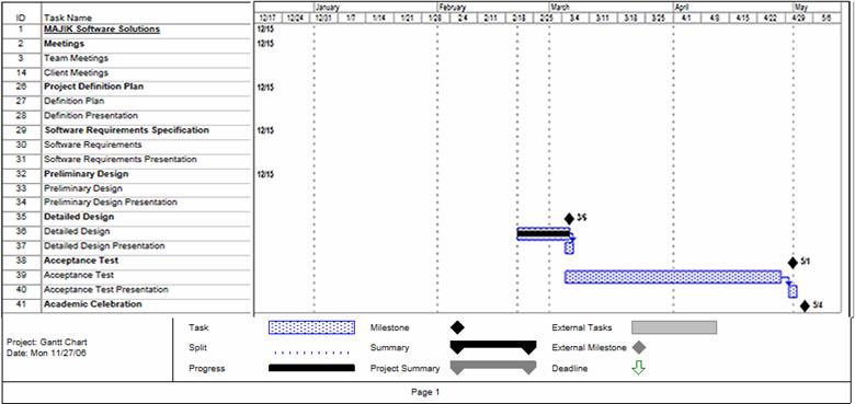
Apache - an open source web server that
runs on most commonly used platforms.
CPU
- Central Processing Unit – The processing component of a computer to
process data.
Data
Flow Diagram - A graphical breakdown of the processes and major flows of
data that occur in the system.
Database
– A collection of data organized to be readily available for use.
Gantt
Chart - A chart that displays progress over time, in this case used to keep
track of a project.
IP address – Internet Protocol address,
is a unique address that certain electronic devices use in order to identify
and communicate with each other on a computer network.
Linear
Sequential Model / Classic Waterfall Model – A systematic,
sequential approach to software development that progresses from this Software
Plan to Requirement Specifications, Preliminary/Detailed, and finally
Acceptance Tests.
MAC
address - Media Access Control address, given to a device in a network. It
consists of a 48-bit hexadecimal number (12 characters). The address is
normally assigned to a device, such as a network card, when it is manufactured.
MySql - Open source relational database
management system (RDBMS) that uses Structured Query Language (SQL), a popular
language for adding, accessing, and processing data in a database.
Network
Device - A computer, peripheral or other related communications equipment
attached to a network.
Oracle - a relational database
management system (RDBMS) developed and copyrighted by the Oracle Corporation.
PHP
– A scripting language useful in the creation of dynamic web pages.
Prototype
– A rudimentary depiction of the design of the final product.
Virtual
- Something which is a representation rather than the ‘real’ thing, thus
‘virtual reality’.